Vibration Damping Mechanism And Electronic Device Having The Damping Mechanism

a technology electronic device, which is applied in the direction of domestic cooling apparatus, electrical apparatus casing/cabinet/drawer, instruments, etc., can solve the problems of unsatisfactory heat dissipation effect, computer system crash or hang, and it is not possible to dispose of vibration damping mechanism between hard disks. , to achieve the effect of increasing the area of contact, enhancing heat dissipation efficiency, and good heat dissipation

Inactive Publication Date: 2009-08-06
AOPEN
View PDF6 Cites 18 Cited by
  • Summary
  • Abstract
  • Description
  • Claims
  • Application Information

AI Technical Summary

Benefits of technology

[0023]In the vibration damping mechanism of this invention, the arrangement of the heat sink for supporting the hard disk allows the bottom face of the hard disk to completely lie flat and abut against the top face of the heat conducting plate of the heat sink to effectively increase the area of contact between the hard disk and the heat sink for enhancing the heat transfer efficiency. Such arrangement, in combination with the arrangement of the heat-dissipating fins of the heat sink that are exposed from the frame through the opening to per

Problems solved by technology

If problems associated with heat dissipation of the hard disk and effects of vibration of a computer housing that is subjected to an external force on the hard disk cannot be effectively solved, the computer system may crash or hang.
However, heat dissipated from the hard disk 13 by the heat sink 14 still remains in the interior of the computer 1, so that the heat dissipating effect is unsatisfactory.
However, since such an arrangement requires the hard disk 13 to be tightly attached to the thermal pad 16, it is not possible to dispose a vibration damping mechanism between the hard disk 13 and the frame 15.
However, mounting of the fans 18 on the hard

Method used


Image

  • Vibration Damping Mechanism And Electronic Device Having The Damping Mechanism
  • Vibration Damping Mechanism And Electronic Device Having The Damping Mechanism
  • Vibration Damping Mechanism And Electronic Device Having The Damping Mechanism

Examples


Embodiment Construction

[0033]It is noted herein that, in the following description, directional terms, such as top, bottom, left, right, front, and rear, are defined in relation to the drawings, and are intended to facilitate description of the present invention rather than limit the scope of the present invention.

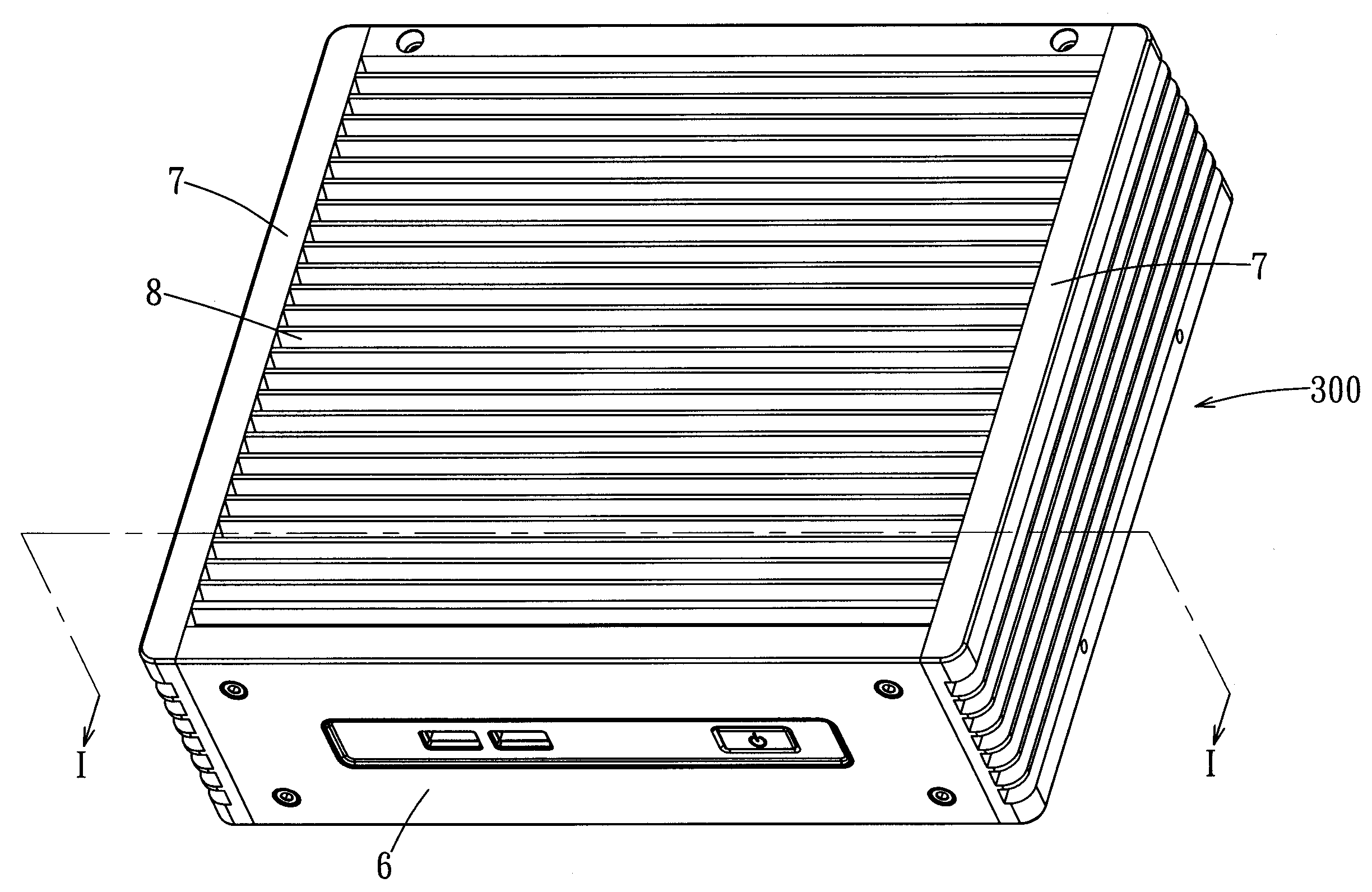
[0034]FIGS. 5 and 6 show a preferred embodiment of an electronic device 300 having a vibration damping mechanism 3 according to the present invention. The electronic device 3 is a fanless computer, and includes the vibration damping mechanism 3, a hard disk 4, a motherboard 5, a face panel 6, two side panels 7, and a top panel 8.

[0035]As shown in FIGS. 5, 6 and 7, the vibration damping device 3 includes a frame 31, a plurality of cushioning members 32, a heat sink 33, a plurality of fastening members 34, and a plurality of screws 35. The frame 31 is formed from a metal material, and has a base plate 311 and a plurality of supporting arms 313. The frame 31 defines a receiving space 312. The base ...


PUM

PropertyMeasurementUnit
Weightaaaaaaaaaa
Lengthaaaaaaaaaa
Sizeaaaaaaaaaa

Abstract

A vibration damping mechanism includes a frame, cushioning members, a heat sink, and fastening members. The frame has a base plate and supporting arms disposed on the base plate. Each cushioning member is disposed on a respective one of the supporting arms, and has a through hole. The heat sink supports a hard disk thereon such that the hard disk lies flat against and is secured on the heat sink, and has a plurality of fastening holes. Each fastening member extends through the respective through hole and threadedly engages the respective fastening hole such that the heat sink is suspended on the supporting arms and abuts against the cushioning members. Thus, the area of contact between the heat sink and the hard disk is increased to enhance the heat transfer efficiency, and the cushioning members provide the heat sink and the hard disk with a cushioning effect.

Description

CROSS-REFERENCE TO RELATED APPLICATION[0001]This application claims priority of Taiwanese Application No. 097202594, filed on Feb. 5, 2008.BACKGROUND OF THE INVENTION[0002]1. Field of the Invention[0003]The invention relates to a vibration damping mechanism, more particularly to a vibration damping mechanism for mounting of a hard disk thereon and capable of providing the hard disk with good heat dissipating and vibration damping functionalities, and to an electronic device having the vibration damping mechanism.[0004]2. Description of the Related Art[0005]A hard disk is a dynamic component in a computer system, and is relatively sensitive to heat and vibrations. If problems associated with heat dissipation of the hard disk and effects of vibration of a computer housing that is subjected to an external force on the hard disk cannot be effectively solved, the computer system may crash or hang. Generally, there are several ways of effecting heat dissipation for a hard disk.[0006]With ...

Claims


Application Information

Patent Timeline
IPC IPC(8): G06F1/16
CPCG06F1/20G06F1/187
Inventor CHANG, CHUN
Owner AOPEN
Why Eureka
Try Eureka