

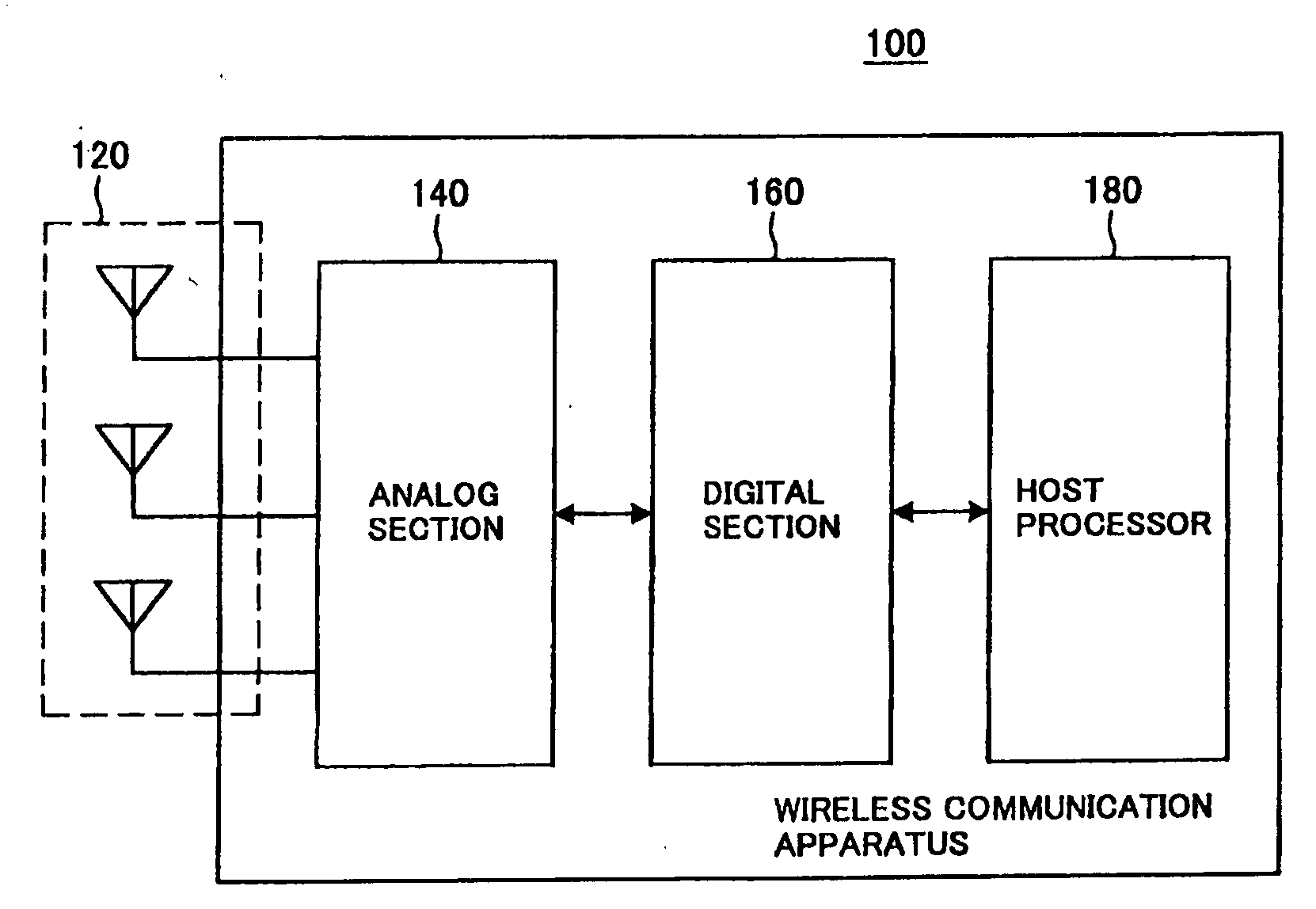
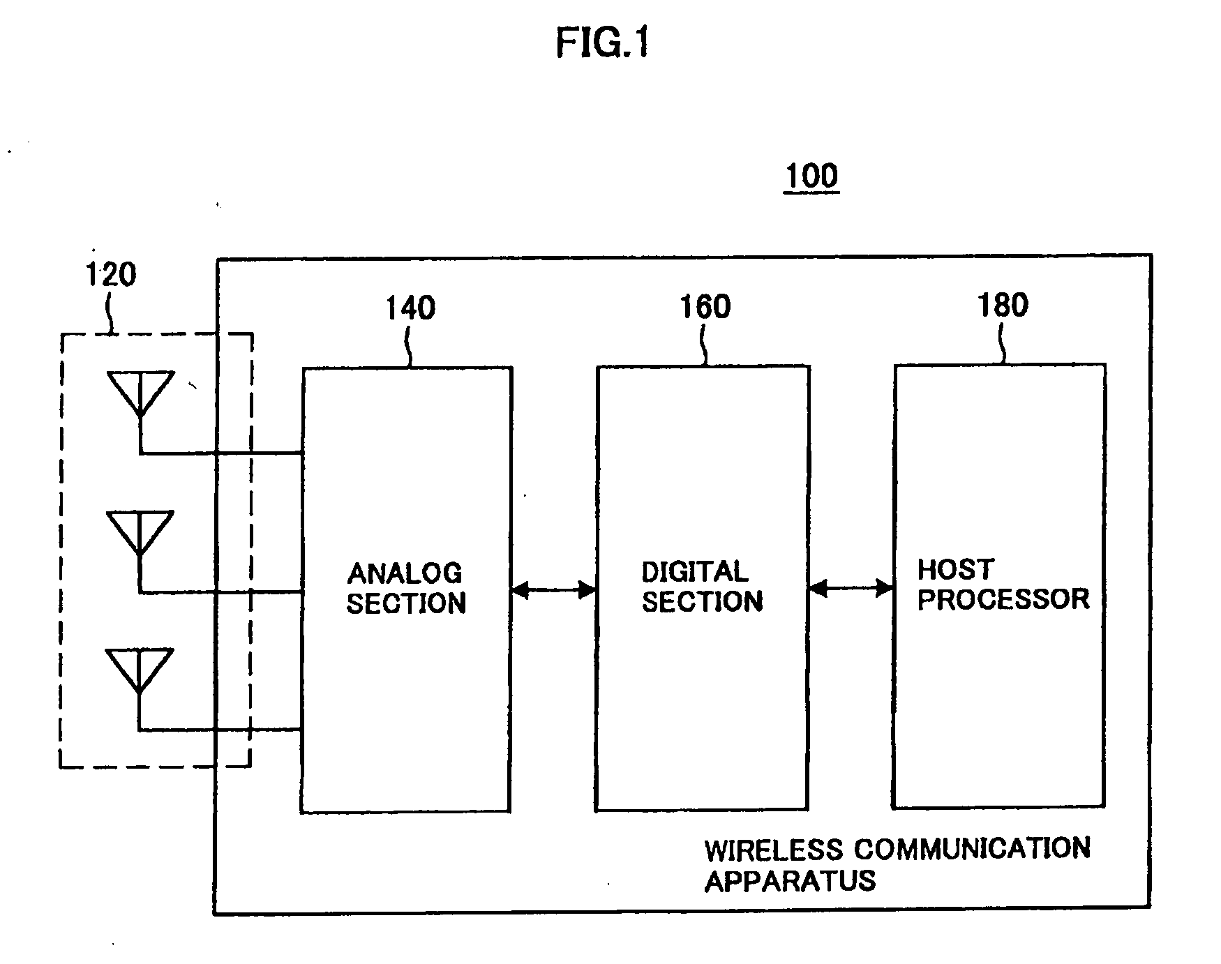
Wireless Communication Apparatus, Antenna Calibration Method and Program
a technology of communication apparatus and antenna, applied in the direction of receiver monitoring, transmission monitoring, baseband system details, etc., can solve the problem of difficult to detect a difference in the transfer function between the analog transmitting section and the analog receiving section
- Summary
- Abstract
- Description
- Claims
- Application Information
AI Technical Summary
Benefits of technology
Problems solved by technology
Method used
Image

Examples
first embodiment
[0071]In light of this, it is proposed to use a first acquisition method described hereinbelow. In the first acquisition method proposed below, a signal corresponding to the reference signal matrix X1 shown in the following expression 8 is transmitted as a reference signal.
X1=[Ref000Ref000Ref]Expression8
[0072]The reference signal represented by the reference signal matrix X1 is a 3×3 scalar matrix. Although the matrix element Ref of the reference signal matrix X1 may be any of an actual number and a complex number, the case where Ref=1 is described hereinafter by way of illustration.
[0073]The reference signal matrix X1 is obtained by transmitting the reference signal after dividing the region of the reference signal into three in one transmission packet. Specifically, the reference signal is transmitted from the branch 1 in the state where the branch 2 is in the transmitting mode and the transmission data of the branch 2 is 0, and the reference signal is transmitted from the branch ...
second embodiment
[0080]Although the first acquisition method can acquire the transfer functions b and c, there is an issue of the setting of a gain value when receiving a transmission packet in the branch 0. Specifically, it is relatively difficult to calculate a gain value (AGC (Automatic Gain Control) fixed value) that is commonly set when a difference between the transfer function b and the transfer function c is large.
[0081]In light of this, it is proposed to use a second acquisition method described hereinbelow. In the second acquisition method proposed below, a signal represented by a product P1X1 of the reference signal matrix X1 shown in the above expression 9 and a matrix P1, which is shown in the following expression 10, is transmitted as a reference signal.
P1X1=[1111exp(-j2π / 3)exp(-j4π / 3)1exp(-j4π / 3)exp(-j2π / 3)][100010001]=[1111exp(-j2π / 3)exp(-j4π / 3)1exp(-j4π / 3)exp(-j2π / 3)]Expression10
[0082]The matrix P1 is a 3×3 matrix of full rank in which the inner product of the column vectors is 0, t...
PUM
 Abstract
Description
Claims
Application Information