Electrostatic spray nozzle, and nanomaterial immobilization apparatus and immobilization method using the same

Inactive Publication Date: 2009-08-06
HAMAMATSU PHOTONICS KK
View PDF8 Cites 12 Cited by
  • Summary
  • Abstract
  • Description
  • Claims
  • Application Information

AI Technical Summary

Benefits of technology

[0016]Furthermore in such nanomaterial immobilization, the nozzle including the nozzle body and the core structure is used as the electrostatic spray nozzle. By using such a nozzle, the nanomaterial dispersion liquid is supplied reliably to the tip of the nozzle body by the capillary action at the core structure. The nozzle bore diameter can thus be made small to lessen the number of particles of the nanomaterial contained in the droplet sprayed to thereby suppress aggregation of the nanomaterial and enable the nanomaterial to be immobilized favorably on the sample.
[0017]With the above-described electrostatic spray nozzle and t

Problems solved by technology

However, with this method, the nanomaterial aggregates in a process of drying a solvent after coating of the nanomaterial dispersion liquid, and consequently, inherent characteristics of the nanomaterial ca

Method used


Image

  • Electrostatic spray nozzle, and nanomaterial immobilization apparatus and immobilization method using the same
  • Electrostatic spray nozzle, and nanomaterial immobilization apparatus and immobilization method using the same
  • Electrostatic spray nozzle, and nanomaterial immobilization apparatus and immobilization method using the same

Examples


first embodiment

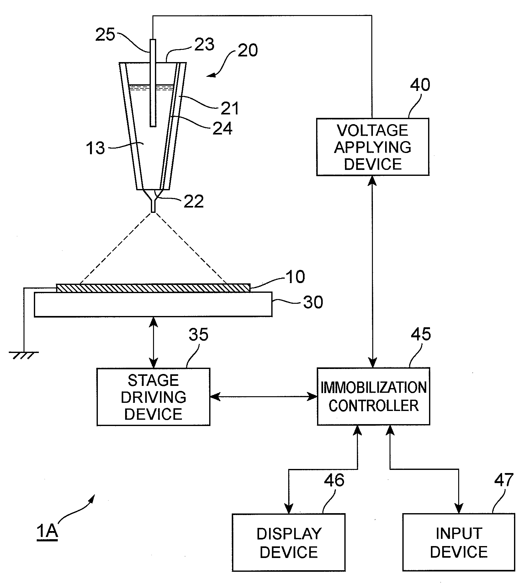
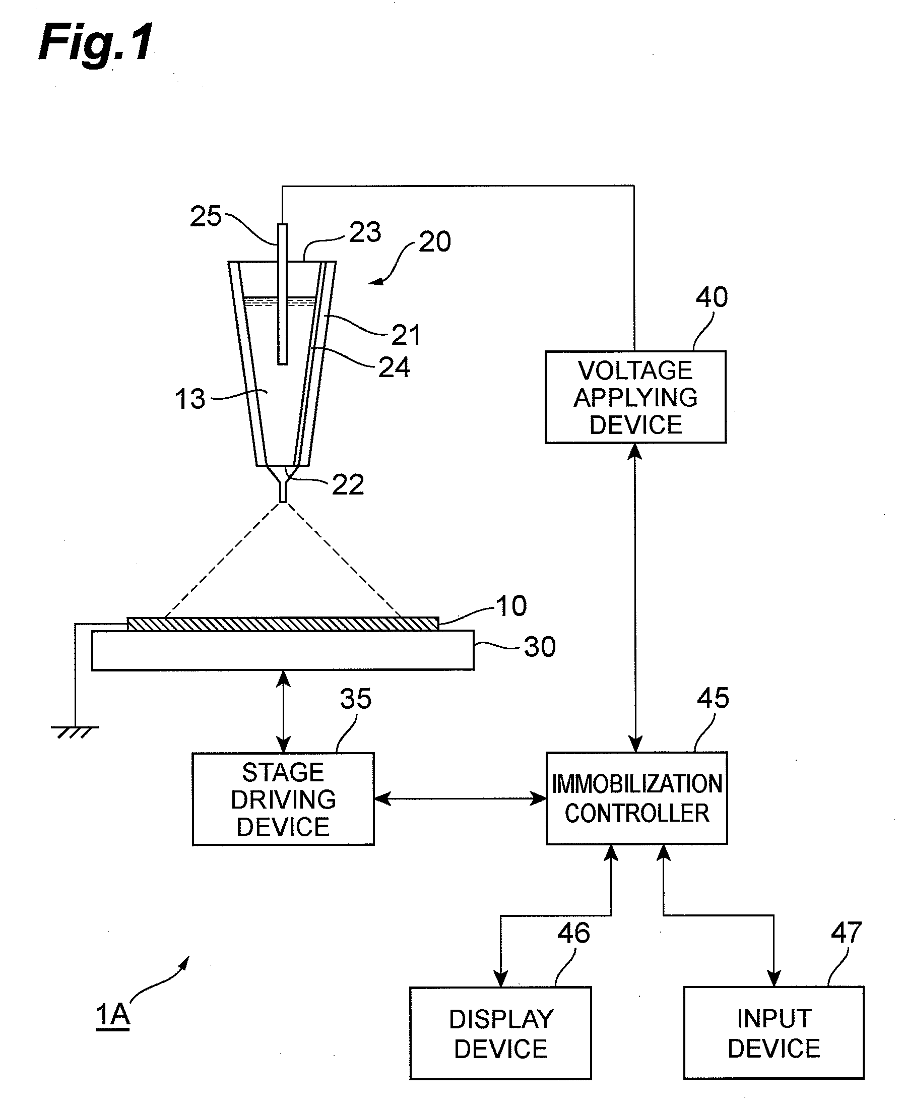
[0038]FIG. 1 is a schematic block diagram of a configuration of a nanomaterial immobilization apparatus including an electrostatic spray nozzle according to the present invention. The nanomaterial immobilization apparatus 1A according to the present embodiment immobilizes a nanomaterial on a surface of a bulk material by using a nanomaterial dispersion liquid, in which the nanomaterial is dispersed in a solvent, and electrostatically spraying the dispersion liquid. In the following description, a sample is a bulk material of substrate form or other predetermined shape that is a target of nanomaterial immobilization. As the nanomaterial subject to the immobilization process, a microscopic material with a size not more than 100 mm (for example, nanoparticles with a diameter not more than 100 nm) is preferably used. Such a microscopic material exhibits physical properties (optical characteristics, electrical characteristics, physical characteristics, etc.) that differ from those of nor...

second embodiment

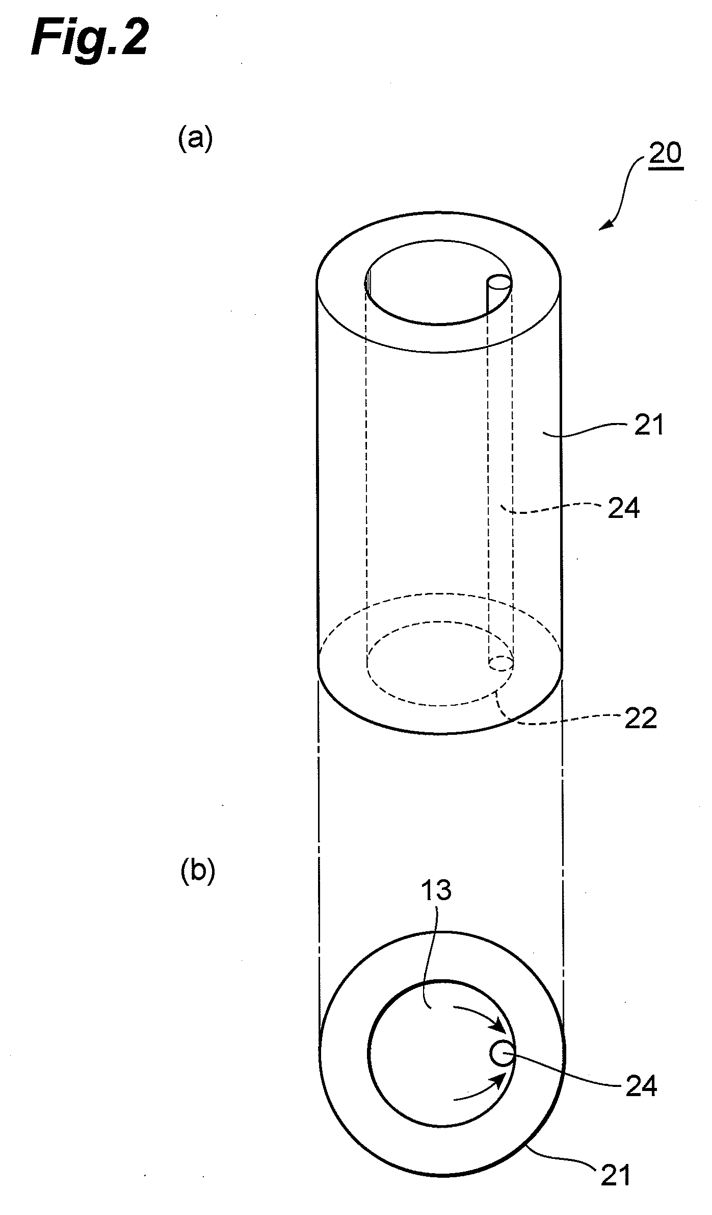
[0104]FIG. 14 is a schematic block diagram of a configuration of a nanomaterial immobilization apparatus according to the present invention. In regard to the electrostatic spray nozzle 20, including the nozzle body 21 and the core structure 24, the sample stage 30 on which the sample 10 is set, the stage driving device 35, and the voltage applying device 40, the configuration of the nanomaterial immobilization apparatus 1B according to the present embodiment is the same as that of the immobilization apparatus 1A shown in FIG. 1.

[0105]The nanomaterial immobilization apparatus 1B shown in FIG. 14 includes a photodispersion laser light source 50 irradiating the nanomaterial dispersion liquid 13 in the interior of the nozzle body 21 with photodispersion laser light for dispersing aggregated nanomaterial. With this configuration, even if the nanomaterial that is dispersed in the solvent aggregates in the dispersion liquid 13 before electrostatic spraying, the nanomaterial can be redisper...


PUM


Abstract

In regard to a nozzle 20, used for electrostatic spraying of a nanomaterial dispersion liquid 13, in which a nanomaterial is dispersed in a solvent, the nozzle 20 includes: a nozzle body 21, having a tubular structure capable of storing the nanomaterial dispersion liquid 13 in an interior thereof and having a dispersion liquid spray outlet 22 disposed at a tip thereof; and a rod-like core structure 24, disposed in an interior of the nozzle body 21. The core structure 24 extends in a predetermined range, including the spray outlet 22, along a longitudinal direction of the nozzle body 21 in a state of contacting an inner wall of the nozzle body 21. By using such an electrostatic spray nozzle 20, immobilization on a sample can be performed favorably while suppressing aggregation of the nanomaterial.

Description

BACKGROUND OF THE INVENTION[0001]1. Field of the Invention[0002]The present invention relates to an electrostatic spray nozzle used for spraying a dispersion liquid in which a nanomaterial is dispersed in a solvent, and to a nanomaterial immobilization apparatus and immobilization method using the electrostatic spray nozzle.[0003]2. Related Background of the Invention[0004]With recent advances in nanotechnology, a wide variety of nanomaterials have been created. Because new characteristics not seen in normal, bulk body materials are expressed in nanomaterials due to effects of their ultramicroscopic size, etc., nanomaterials are anticipated for utilization in various fields and applications.[0005]Unlike bulk materials, the above-described nanomaterials are difficult to handle due to being extremely small and have a property that a plurality of nanomaterials aggregate readily to form aggregates. Thus in many cases, nanomaterials are handled in a state of a nanomaterial dispersion liq...

Claims


Application Information

Patent Timeline
IPC IPC(8): B05D1/04B05B5/025
CPCB05B5/0255B05D1/04B05B12/082
Inventor KAWAKAMI, TOMONORI
Owner HAMAMATSU PHOTONICS KK
Why Eureka
Try Eureka