

Method of boring glass substrate and glass substrate for plasma display manufactured by the method
- Summary
- Abstract
- Description
- Claims
- Application Information
AI Technical Summary
Benefits of technology
Problems solved by technology
Method used
Image

Examples
example
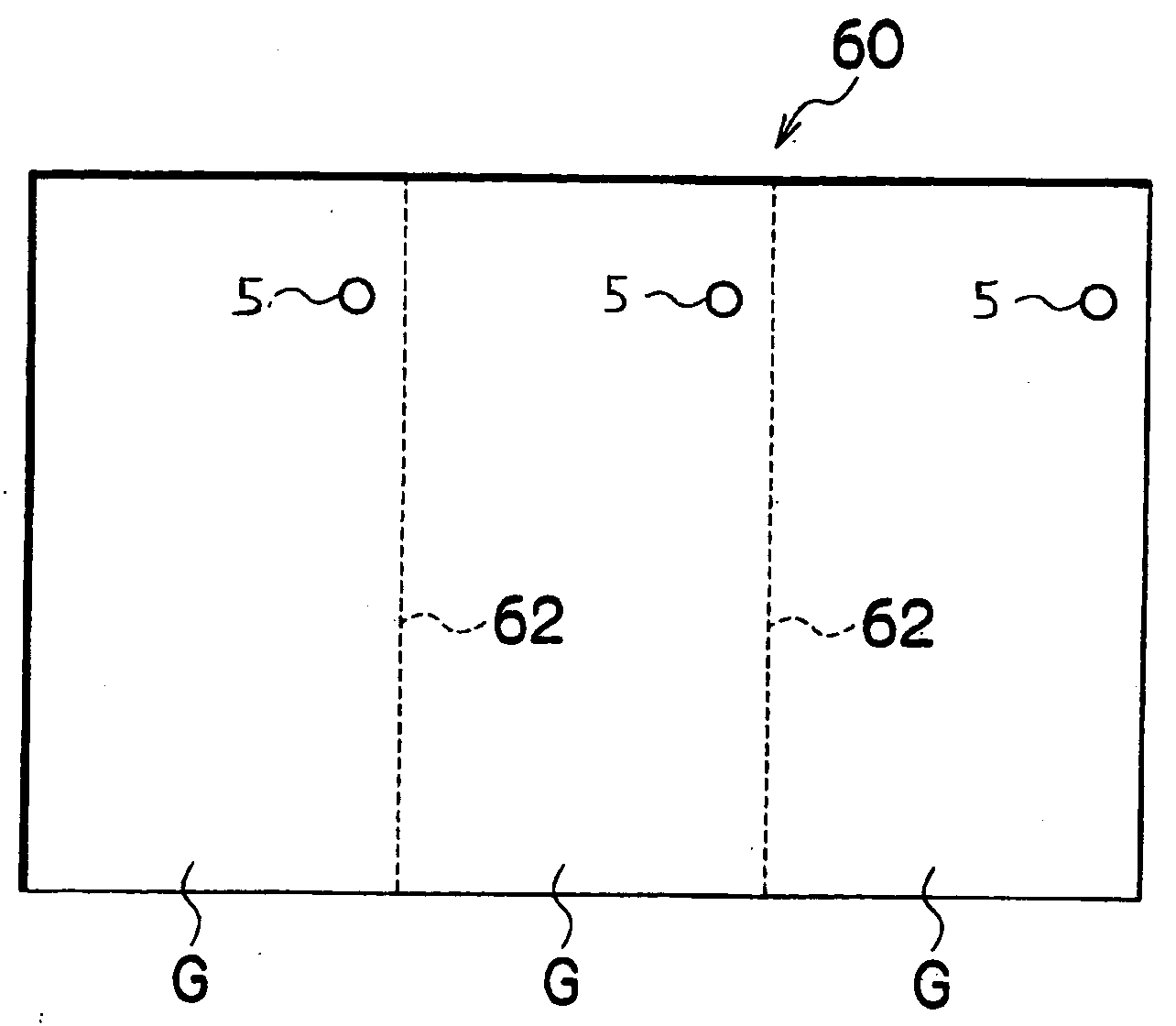
[0049]A total of 60 samples were prepared by opening the through hole 5 with a diameter of 2 mm at positions spaced 11.5 mm away from respective two orthogonal end faces of an essentially-rectangular PDP glass substrate G measuring 150×150 mm and having a thickness of 1.8 mm, in which the step 6 to appear on the through hole 5 was made at a position spaced 1.7 mm from the bottom surface B of the glass substrate G. In seven samples of them, the steps 6 were made at intervals of 0.1 mm downward from a position 1.7 mm away from the bottom surface up to a position of 1.0 mm. In four of the samples, the step 6 was made at a position 0.9 mm away from the bottom surface B of the glass substrate G. In relation to the samples, the glass substrates G were heated for ten minutes (at about 280 degrees: where a temperature difference of about 170 degrees between the top surface and the bottom surface is achieved) while the bottom surfaces B were placed on the heater held at a high temperature (a...
PUM
| Property | Measurement | Unit |
|---|---|---|
| Depth | aaaaa | aaaaa |
Abstract
Description
Claims
Application Information