Digital Excitation Control System Utilizing Swarm Intelligence and An Associated Method of Use

a control system and digital excitation technology, applied in the direction of electric controllers, dynamo-electric converter control, instruments, etc., can solve the problems of regulating the field strength of main generators, and spherical swarms in main generator outpu

Active Publication Date: 2009-08-06
BASLER ELECTRIC
View PDF14 Cites 48 Cited by
  • Summary
  • Abstract
  • Description
  • Claims
  • Application Information

AI Technical Summary

Benefits of technology

[0015]In yet another aspect of the present invention, the calculated PID gains are fixed during commissioning. Preferably, no further tuning is conducted during normal operation. One benefit of this approach is that no supervision is needed to prevent undesirable responses caused by a transient behavior of the PID gain estimation.

Problems solved by technology

Thus, the problem of regulating the main generator field strength is typically achieved by regulating the output of the exciter generator.
Overshoot occurs when the controller provides too much current, thereby causing a “spike” in main generator output.
Undershoot occurs when the controller provides too little current, thereby causing a “dip” in main generator output.
A poorly tuned PID controller will result in poor performance, e.g., overshoot, undershoot, or slow response time.
When a motor is powered by a generator, the motor presents a large load while the motor is starting, which can cause the generator output voltage to dip.
A dip in generator output voltage can cause damage to the motor as the motor will increase its current consumption and heats up due to resistive heating within the motor.
In general, since the calculation of loop gain requires several excitation system parameters that are generally not available during commissioning, e.g., specifically the machine time constant, this lack of information increases commissioning time.
Under these conditions, commissioning a new voltage regulator becomes a challenging task.
Trial-and-error is tedious and adds significantly to commissioning time.
One difficulty in regulating the voltage output of a generator arises due to the inductive properties of a coil of wire, such as a field coil winding.
Since the excitation system and the generator contain inductive coils, there is a time delay between a change in output voltage from the voltage regulator and the corresponding change in generator output voltage.
For example, the relative accuracy of a two percent (2%) step response test becomes about a ten percent (10%) error in measurement.
Therefore, in this case, it is difficult to identify the exciter and generator time constants.
Experiments show very slow convergence speed in identification, which is much slower than today's fast excitation system requirements.

Method used


Image

  • Digital Excitation Control System Utilizing Swarm Intelligence and An Associated Method of Use
  • Digital Excitation Control System Utilizing Swarm Intelligence and An Associated Method of Use
  • Digital Excitation Control System Utilizing Swarm Intelligence and An Associated Method of Use

Examples


Embodiment Construction

[0038]In the following detailed description, numerous exemplary specific details are set forth in order to provide a thorough understanding of the invention. However, it will be understood by those skilled in the art that the present invention may be practiced without these specific details, or with various modifications of the details. In other instances, well known methods, procedures, and components have not been described in detail so as not to obscure the present invention.

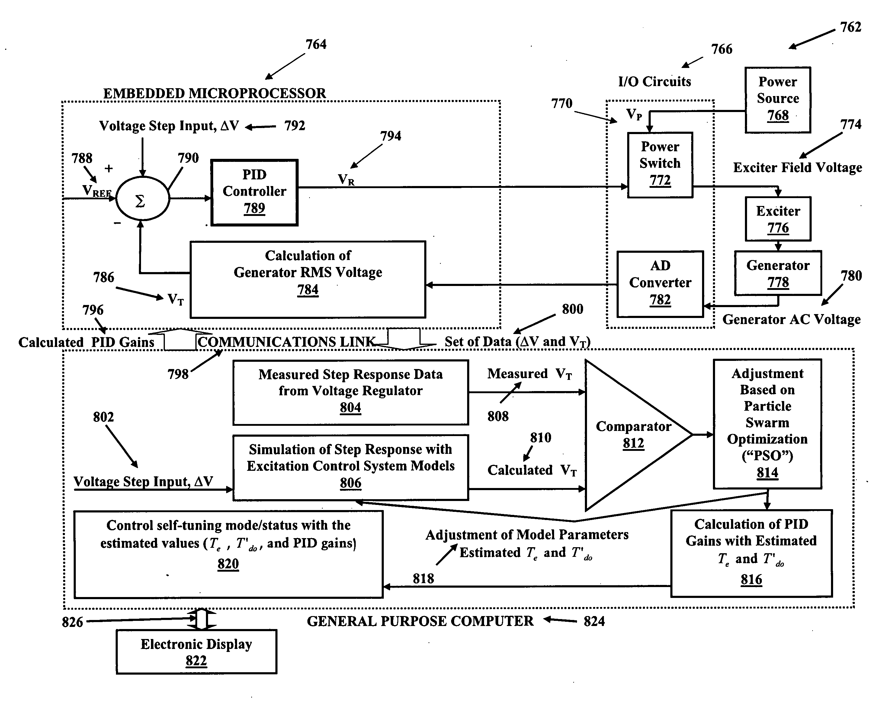
[0039]Referring now to FIG. 3, the basic block diagram of a self-exciting excitation control system with exemplary PID block utilized in an automatic voltage regulator control loop is generally indicated by numeral 10. In addition to the PID block 20, the system loop gain KG 18 provides an adjustable term to compensate for variations in system input voltage to a power converting bridge. The transfer function Gc(s) of the PID controller 20 may be expressed as

GC=KGVP(KP+KIs+KDs1+TDs),

where KG is loop gain, KP i...


PUM


Abstract

A system and method of use for self-tuning a PID controller utilized with an exciter and generator is disclosed. The system includes a power source, an exciter electrically connected to the power source, a generator that is electrically energized by the exciter, and a processor that provides a PID controller that calculates an estimated exciter time constant and an estimated generator time constant using particle swarm optimization (“PSO”) to control exciter field voltage. The particle swarm optimization (“PSO”) technique includes increasing the voltage reference by a predetermined percentage over a predetermined time period, initializing each particle position of exciter time constant and generator time constant, calculating generator voltage, performing a fitness evaluation and then obtaining and updating best values. This is followed by repeating the steps of determining the generator voltage, the fitness evaluation, and the best values over a predetermined number of iterations.

Description

CROSS-REFERENCE TO RELATED APPLICATION[0001]This application is a continuation-in-part of U.S. patent application Ser. No. 12 / 023,145, filed on Jan. 31, 2008, which is incorporated herein by reference in its entirety.BACKGROUND OF THE INVENTION[0002]An electrical generator typically operates by rotating a coil of wire relative to a magnetic field (or vice versa). In modern electrical generators, this magnetic field is typically generated using electromagnets known as field coils. An electrical current in these field coils provides the magnetic field necessary to induce an electrical current in the main generator coil. The current and voltage output of the main generator depends on the current in the field coils. Thus, as the generator load changes, the magnetic field strength must be adjusted in an attempt to maintain constant generator output. This is achieved by regulating the current in the field coils. Thus, it is desirable to regulate continuously the current in the field coils...

Claims


Application Information

Patent Timeline
Patent Type & Authority Applications(United States)
IPC IPC(8): G06F1/28H02P9/30G06G7/63G06G7/66
CPCH02P9/102G05B11/42G05B13/044
Inventor KIM, KIYONGRAO, PRANESHBURNWORTH, JEFF
Owner BASLER ELECTRIC
Why Eureka
Try Eureka