Devices with internal flexibility sipes, including siped chambers for footwear

a technology of flexible sipes and devices, applied in the field of all forms of footwear, can solve the problems of affecting the rigidity of products interfacing directly with them, and the degradation of the support and cushioning of the bare foot, so as to increase the flexibility of the device, and improve the comfort of the foo

Active Publication Date: 2009-08-13
ELLIS
View PDF99 Cites 41 Cited by
  • Summary
  • Abstract
  • Description
  • Claims
  • Application Information

AI Technical Summary

Benefits of technology

[0019]In one aspect the present invention attempts, as closely as possible, to replicate the naturally effective structures of the bare foot that provide flexibility, cushioning, and stable support. More specifically, the invention relates to a device for a footwear sole or upper or both, or an orthotic or orthotic upper or both, or other, non-footwear devices, including a unitary internal sipe component, said internal sipe providing increased flexibility for said device. More specifically, the invention relates to an integral component with at least one sipe with a media such as a lubricant or glue of any useful characteristic such as viscosity or any material, including a magnetorheological fluid.
[0020]Even more specifically, the invention relates to footwear or orthotics or other products with at least one compartment or chamber or bladder surrounded, partially or completely, by at least one internal (or mostly internal) sipe for use in any footwear soles or uppers, or orthotic soles or uppers, and for other flexibility, cushioning, and stability uses. Even more specifically, the invention relates to footwear, orthotic or other products with at least one outer chamber; at least one inner chamber inside the outer chamber; the outer chamber and the inner chamber being separated at least in part by an internal sipe; at least a portion of an inner surface of the outer chamber forming at least a portion of an inner surface of the internal sipe; and the internal sipe providing increased flexibility, cushioning, and stability for the footwear, orthotic or other product.

Problems solved by technology

Existing devices are generally much less flexible than would be optimal, especially products for human (or animal) users, whose non-skeletal anatomical structures like bare foot soles generally remain flexible even under significant pressure, whereas the products interfacing directly with them are often much more rigid.
As a result, the support and cushioning of the bare foot are seriously degraded when shod in existing footwear, since the relatively rigid shoe sole drastically alters by obstructing the way in which the bare foot would otherwise interact with the ground underneath a wearer.
External sipes are structurally unlike natural anatomical structures (since to be effective, they must be much deeper than surface skin texture like finger prints, the closest anatomical analogy), however, and tend to introduce significant instability by creating excessive shoe sole edge weakness adjacent the sipes, while also collecting debris in the sipes, both seriously reducing their performance.
In addition, the optimal pattern and depth of such sipes is difficult to ascertain directly and tends to be a trial and error process guided by guessing, rather than the much easier procedure of following the design of the anatomical structure with which it is intended to interface to create natural flexibility.
This approach requires completely new and somewhat difficult approaches in the assembly of the footwear sole during manufacture, as well as significantly greater potential for problems of layer separation (especially bottom sole) since the inherent reduction in gluing surfaces makes the remaining gluing surfaces critical and under increased load; significantly increased positional accuracy in the application of glue is required.
Also, the use of lubricating media (and the potential control thereof, including by microprocessor) is also more difficult, since the sipe is formed by existing parts and is not discretely enclosed with the new outer layer to contain the media, as it is in the new invention described in this application.

Method used


Image

  • Devices with internal flexibility sipes, including siped chambers for footwear
  • Devices with internal flexibility sipes, including siped chambers for footwear
  • Devices with internal flexibility sipes, including siped chambers for footwear

Examples


Embodiment Construction

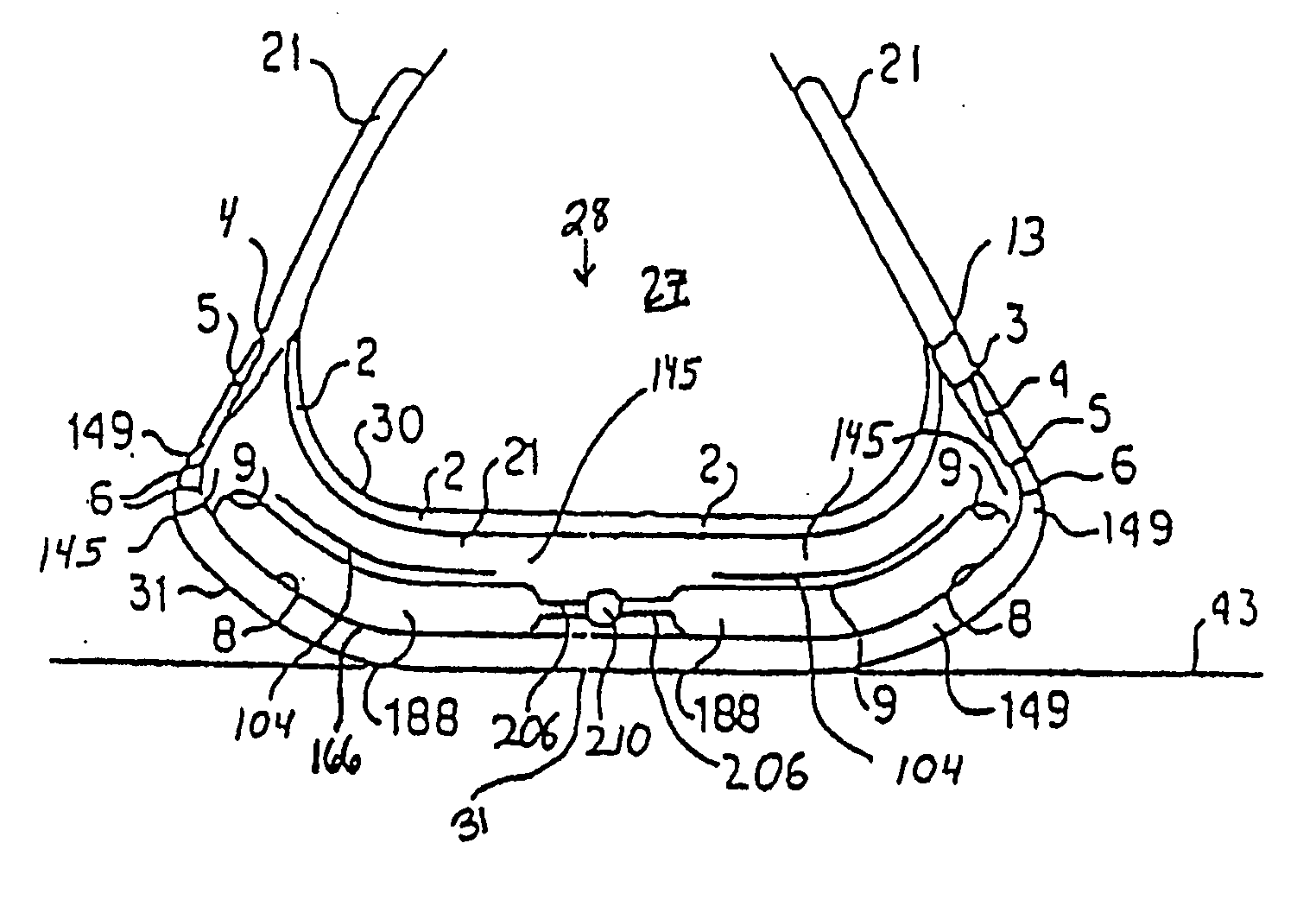
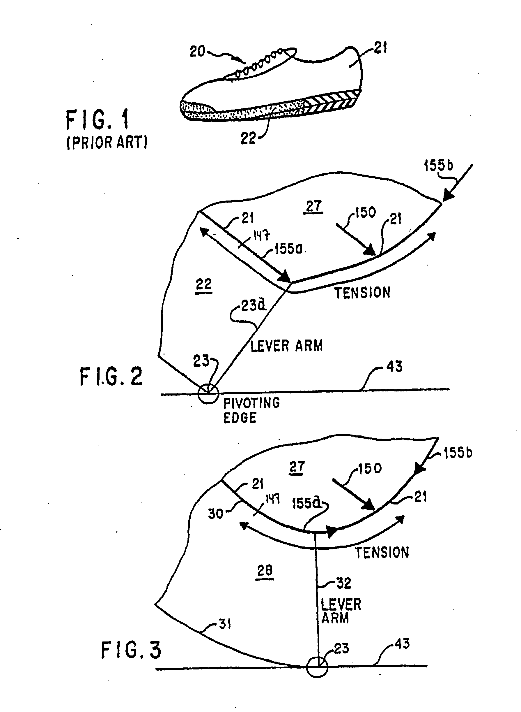
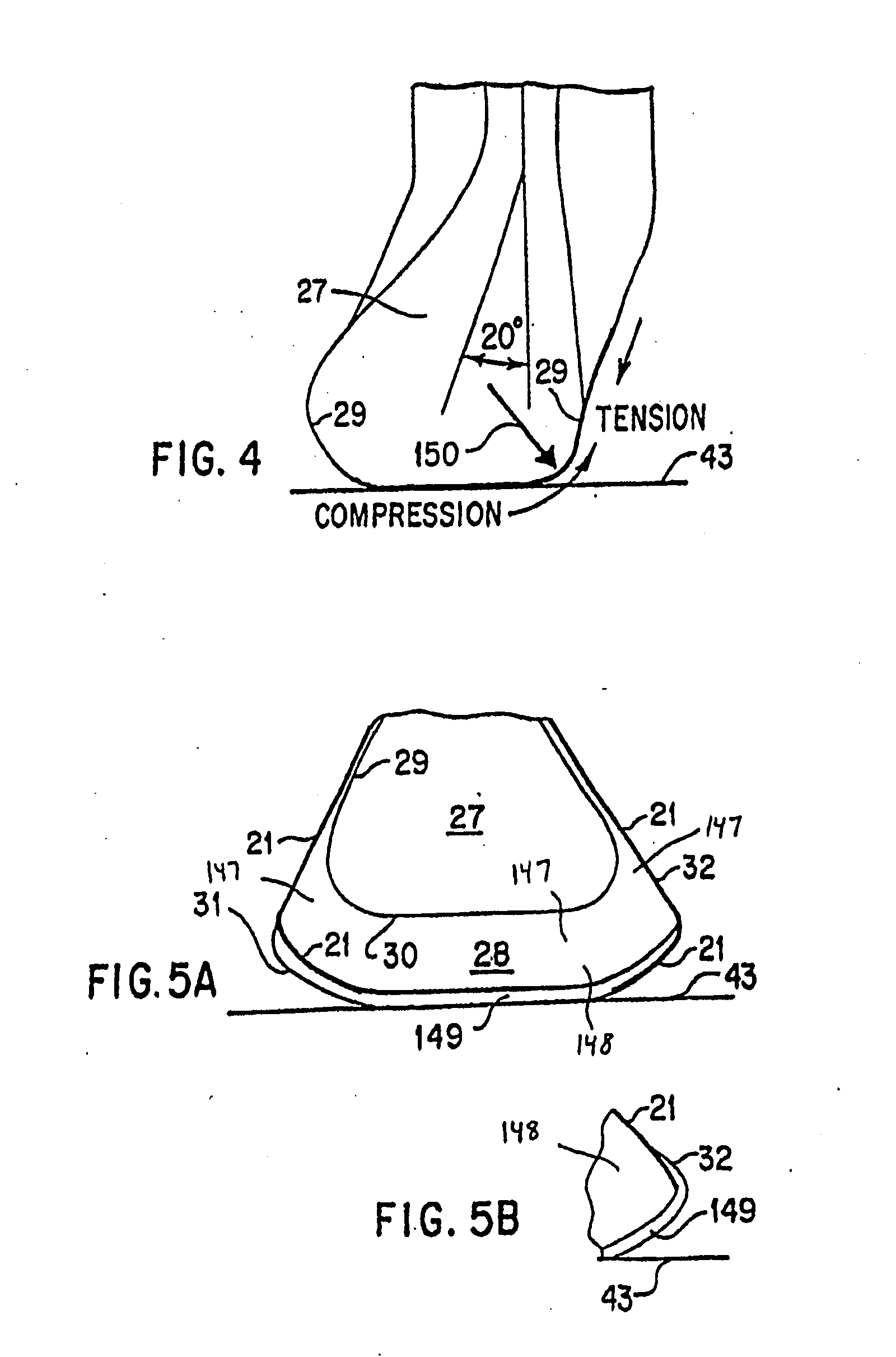
[0180]All reference numerals used in the figures contained herein are defined as follows:

Ref. No.Element Description 2insole 3attachment point of upper midsole and shoe upper 4attachment point of bottom sole and shoe upper 5attachment point of bottom sole and upper midsole 6attachment point of bottom sole and lower midsole 8lower surface interface of removable midsole section 9interface line between encapsulated sectionand midsole sections 11lateral stability sipe 12medial stability sipe 13interface between insole and shoe upper 14medial origin of the lateral stability sipe 16hatched area of decreased area of footprintdue to pronation 17footprint outline when tilted 18inner footprint outline of low arched foot 19hatched area of increased area of footprintdue to pronation 20athletic shoe 21shoe upper 21ainner or secondary shoe upper 22conventional shoe sole 23bottom outside edge of the shoe sole 23alever arm 26stabilizing quadrants 27human foot 28rounded shoe sole 28arounded stabilit...


PUM


Abstract

The present invention attempts to replicate in footwear, orthotics, and other products the naturally effective anatomical structures like a bare foot that provide superior flexibility, cushioning, and stable support compared to existing products. More specifically, the invention relates to a device for such products including a unitary internal sipe component, said internal sipe providing increased flexibility for said device. Even more specifically, the invention relates to footwear, orthotic or other products with an outer chamber and at least one inner chamber inside the outer chamber; the outer chamber and the inner chamber being separated at least in part by an internal sips; and the internal sipe providing increased flexibility, cushioning, and stability.

Description

BACKGROUND OF THE INVENTION[0001]1. Field of the Invention[0002]The invention relates to all forms of footwear, including street and athletic, as well as any other products benefiting from increased flexibility, better resistance to shock and shear forces, and stable support. More particularly, the invention incorporates devices as a unitary integral component with at least one internal (or mostly internal) sipe, including slits or channels or grooves and any other shape, including geometrically regular or non-regular, such as anthropomorphic shapes, into a large variety of products including footwear using materials known in the art or their current or future equivalent. Still more particularly, the unitary internal sipe component provides improved flexibility to products utilizing them, as well as improved cushioning to absorb shock and / or shear forces, while also improving stability of support, and therefore the siped devices can be used in any existing product that provides or u...

Claims


Application Information

Patent Timeline
Patent Type & Authority Applications(United States)
IPC IPC(8): A43B13/20A61F5/14A43B23/00
CPCA43B3/0005A63B53/047A43B7/1425A43B7/1435A43B7/144A43B7/24A43B13/14A43B13/181A43B13/187A43B13/189A43B13/203A63B53/04A63B53/0466A63B59/0092A43B7/142A63B60/54A43B3/34
Inventor ELLIS, FRAMPTON E.
Owner ELLIS
Why Eureka
Try Eureka