Scalable pyrospin combustor

Inactive Publication Date: 2009-08-13
HAMILTON SUNDSTRAND CORP
View PDF23 Cites 26 Cited by
  • Summary
  • Abstract
  • Description
  • Claims
  • Application Information

AI Technical Summary

Benefits of technology

[0011]Pyrospin effusion holes are formed in at least one of the outer combustor liner and the inner combustor liner. Each pyrospin effusion hole has a down angle and a back angle, which control a swirl flow field about the central axis and promote film c

Problems solved by technology

It has traditionally been difficult, however, to translate this advantage to smaller-scale applications such as portable power generation and remotely-piloted aircraft, where traditional reciprocating piston engines have scale-related benefits.
Engine efficiency is ultimately limited by thermodynamics.
This limits the thermodynamic efficiency according to the difference between hot combustion gas temperature T1, at which work is extracted, and exhaust gas temperature T2, at which waste heat is dispersed to the environment.
The maximum combustion temperature is limited, however, by

Method used


Image

  • Scalable pyrospin combustor
  • Scalable pyrospin combustor
  • Scalable pyrospin combustor

Examples


Embodiment Construction

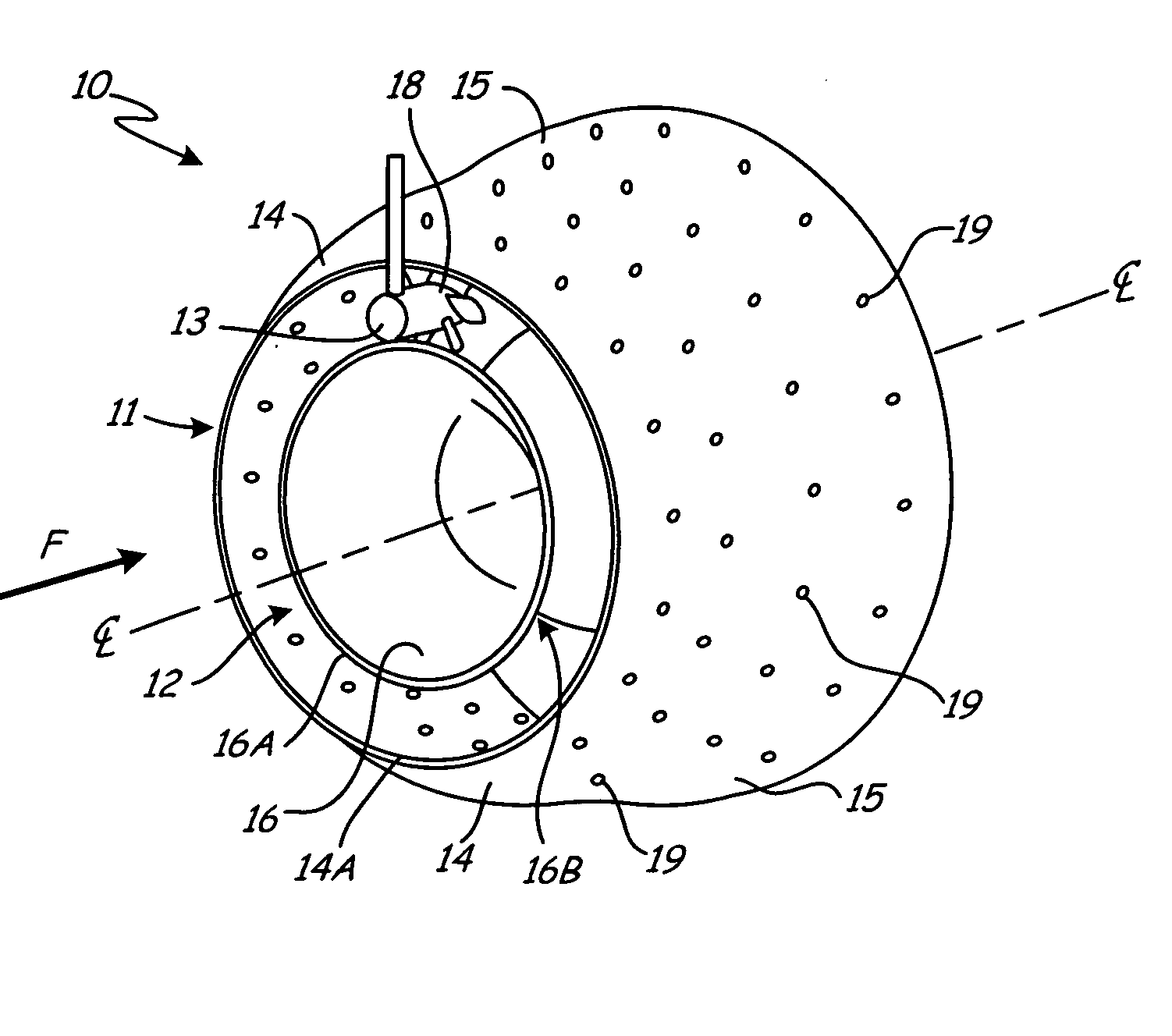
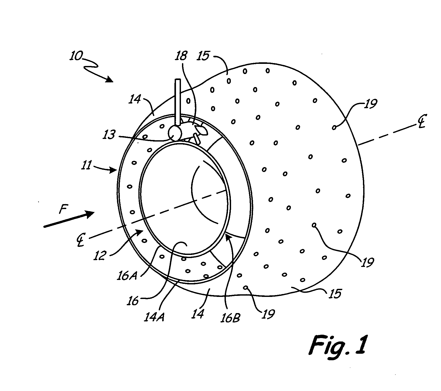
[0016]FIG. 1 is a perspective view showing one embodiment of scalable annular pyrospin combustor 10. Combustor 10 comprises outer combustor liner 11 and inner combustor liner 12, and is configured for axial fuel injection with axial fuel injector 13.

[0017]Outer combustor liner 11 is an outer diameter or OD liner comprising outer dome (or outer dome section) 14 and outer wall (or outer wall section) 15. Outer wall 15 is located in an axially downstream direction with respect to outer dome 14, as indicated by downstream axial combustion flow arrow F. Downstream direction F lies generally along axial centerline (central axis) CL, and indicates the axial component of combustion gas flow through combustor 10.

[0018]Working fluid flows into combustor 10 within OD leading edge 14A of outer dome 14. The radius of outer dome 14 (as measured from centerline CL) increases downstream of leading edge 14A, until outer dome 14 transitions to outer wall 15. The radius of outer wall 15 increases more...


PUM


Abstract

An axial-flow pyrospin combustor comprises inner and outer combustor liners and a plurality of pyrospin effusion holes. The inner liner is coaxially mounted inside the outer liner, about a central combustor axis. The pyrospin effusion holes are formed in at least one of the outer combustor liner and the inner combustor liner. Each of the pyrospin effusion holes has a down angle and a back angle, which control a global swirl flow about the central axis, and promote film cooling without detachment.

Description

BACKGROUND[0001]This invention relates to gas turbine engine combustors, and particularly to annular combustors scalable to small-scale gas turbine engine applications. More specifically, the invention is directed to a scalable, annular combustor with positive combustion control for more efficient combustion.[0002]Fuel efficiency is one of the many advantages of gas turbine engine technology. This is particularly true in larger-scale applications such as industrial gas turbine engines for power generators, and turbofan engines for military and commercial aircraft. It has traditionally been difficult, however, to translate this advantage to smaller-scale applications such as portable power generation and remotely-piloted aircraft, where traditional reciprocating piston engines have scale-related benefits.[0003]Gas turbine engines are typically constructed around a central power core comprising a compressor, a combustor and a turbine. These elements are arranged in flow series, betwee...

Claims


Application Information

Patent Timeline
IPC IPC(8): F23R3/20F02C7/22F02C7/12
CPCF02C7/222F23R3/06F23R3/52F23R2900/03041Y02T50/60
Inventor CHEN, DAIH-YEOU
Owner HAMILTON SUNDSTRAND CORP
Why Eureka
Try Eureka