
Device for mounting an igniter plug in a combustion chamber of a gas turbine engine

a technology of gas turbine engines and igniter plugs, which is applied in the direction of burner ignition devices, machines/engines, lighting and heating apparatus, etc., can solve the problems of significant heating of the chamber ignition zone, poor chamber ignition capability, and difficult reconciliation, so as to improve the longevity of the igniter plugs and facilitate repair

Active Publication Date: 2009-08-13
SN DETUDE & DE CONSTR DE MOTEURS DAVIATION S N E C M A
View PDF7 Cites 19 Cited by
  • Summary
  • Abstract
  • Description
  • Claims
  • Application Information

AI Technical Summary

Benefits of technology

The invention proposes a system for mounting an igniter plug in a gas turbine engine that allows for improved longevity of the igniter plug. The system includes a hollow shaft and a floating igniter plug sleeve that absorbs expansion along the hollow shaft. The hollow shaft sleeve is inclined relative to the igniter plug, allowing the chamber to be inclined relative to the igniter plug. The system also includes means of cooling the igniter plug and means of mounting the hollow shaft sleeve in a way that allows for easy repairs without changing the igniter plug. The invention also relates to a gas turbine engine ignition system and a gas turbine engine comprising the mounting device for the igniter plug.

Problems solved by technology

These two conditions entail arrangements that are difficult to reconcile.
If this angle is a very tight angle then the igniter plug is outside of the cone formed by the fuel; this is preferable from a thermal integrity standpoint but the chamber ignition capability is poor.
Conversely, an injection system in which the sheet of fuel forms a very wide cone causes significant heating of that zone of the chamber that surrounds the igniter plug, because of fuel impinging on the walls and the igniter plug.
This adversely affects the thermal integrity of those elements.
An igniter the end of which protrudes too far into the combustion chamber is exposed to thermal problems.
These thermal problems carry the risk of causing incorrect operation of the engine and, above all, of causing the igniter plug to be destroyed more quickly.
On the other hand, if an igniter plug is set back too far from the wall of the chamber, ignition performance is degraded.
The state of the art means that the axis of the igniter plug always remains perpendicular to the axis of the chamber and there is therefore no ability of the igniter plug to compensate for axial and radial expansion of the chamber.

Method used


Image

  • Device for mounting an igniter plug in a combustion chamber of a gas turbine engine
  • Device for mounting an igniter plug in a combustion chamber of a gas turbine engine
  • Device for mounting an igniter plug in a combustion chamber of a gas turbine engine

Examples


first embodiment

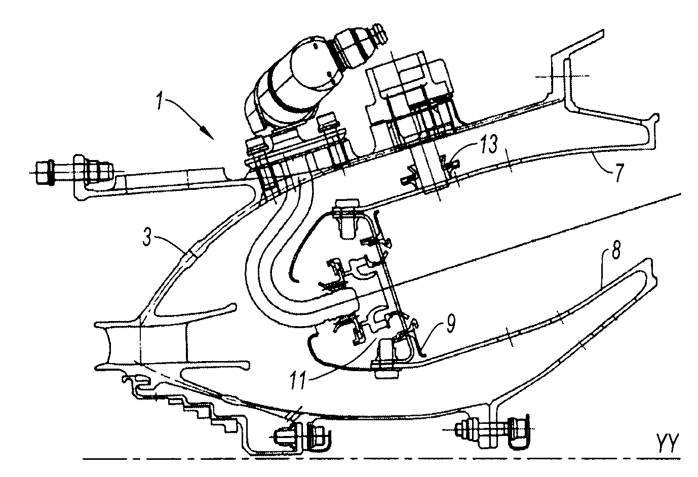
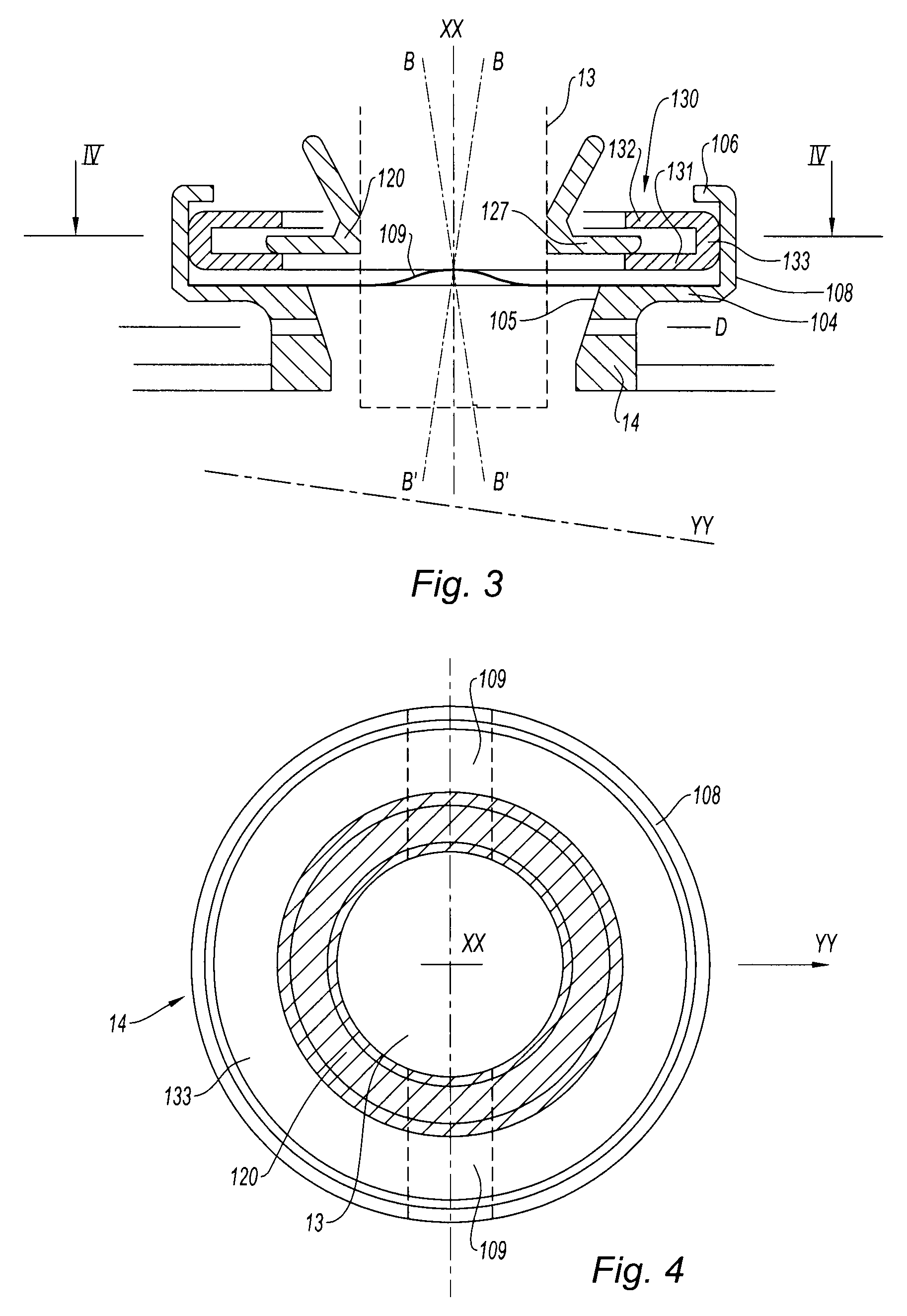
[0023]FIG. 3 shows the device for mounting an igniter plug according to the invention, viewed in section on a plan passing through the axis YY of the chamber.

[0024]This device comprises a hollow shaft 14, of axis XX, which is then fixed to an opening created in the combustion chamber of axis YY. Said hollow shaft is of cylindrical shape (depicted in FIG. 4); its upper part is of a larger diameter than the remainder of the hollow shaft so as to form a flat surface 104, perpendicular to the axis thereof. A cylindrical wall 108 surrounds the flat portion 104 and the upper end 106 of the hollow shaft 14 is shaped in such a way as to form a collar perpendicular to the axis XX.

[0025]This upper part of the hollow shaft 14 houses a hollow shaft sleeve 130. This hollow shaft sleeve 130, which is in the form of a disk, follows the variations in inclination of the chamber with respect to the axis of the igniter plug.

[0026]Two straight strips 109 of rounded shape are created on the flat surface...

second embodiment

[0031]In a second embodiment that has not been depicted, the strips 109 formed on the bottom of the hollow shaft 14 are omitted, the wall of the hollow shaft adopts a spherical shape of a radius slightly greater than that of the wall of the hollow shaft sleeve 130. The hollow shaft sleeve 130 is thus mounted such that it can swivel in the spherical wall of the hollow shaft 14, and its spherical edges allow it to slide along this wall as the chamber becomes inclined with respect to the axis of the igniter plug. According to this embodiment, the hollow shaft sleeve 130 is able to absorb combined variations in inclination between axial and tangential planes of the chamber with respect to the axis of the igniter plug.


PUM


Abstract

The present invention relates to a device for mounting an igniter plug in a combustion chamber of a gas turbine engine contained in a casing, in which the combustion chamber has an axis YY, the mounting device comprising a hollow shaft, of axis XX, a floating igniter plug sleeve absorbing expansion along an axis perpendicular to the axis XX of the hollow shaft. The device is one which further comprises a hollow shaft sleeve such that the igniter plug sleeve is housed in the hollow shaft sleeve, and means of inclining said hollow shaft sleeve relative to the axis XX. Inclining the hollow shaft sleeve allows the chamber to be inclined relative to the axis XX.

Description

[0001]The present invention relates to the field of gas turbine engines and relates more specifically to improving the mounting of an igniter plug in a combustion chamber.BACKGROUND OF THE INVENTION AND DESCRIPTION OF THE PRIOR ART[0002]In a gas turbine engine, the combustion chamber receives air from the compressor, some of which air is mixed with the fuel which is burnt in the primary combustion zone. Ignition is performed by one or two igniter plugs situated downstream of the carburetion system. Another proportion of the air bypasses the primary combustion zone and mixes with the combustion gases. All of the hot gases are then directed toward the turbine. The combustion chambers are designed to meet a certain number of essential specifications such as: in-flight re-ignition, the shape of the temperature profile, the emissions of pollutant gases and the thermal and mechanical integrity of the various components thereof.[0003]In particular, the ignition system has to ensure in-flig...

Claims


Application Information

Patent Timeline
Patent Type & Authority Applications(United States)
IPC IPC(8): F02G3/00
CPCF02C7/266F23R3/60F23D2211/00F23D2207/00F23R3/06F23R2900/00012
Inventor PIEUSSERGUES, CHRISTOPHESANDELIS, DENIS JEAN MAURICE
Owner SN DETUDE & DE CONSTR DE MOTEURS DAVIATION S N E C M A
Learn More