Physical sensor
a sensor and sensor technology, applied in the field of physical sensors, can solve problems such as difficulty in providing a structure, and achieve the effect of improving the spring characteristic and improving the spring characteristi
- Summary
- Abstract
- Description
- Claims
- Application Information
AI Technical Summary
Benefits of technology
Problems solved by technology
Method used
Image

Examples
first embodiment
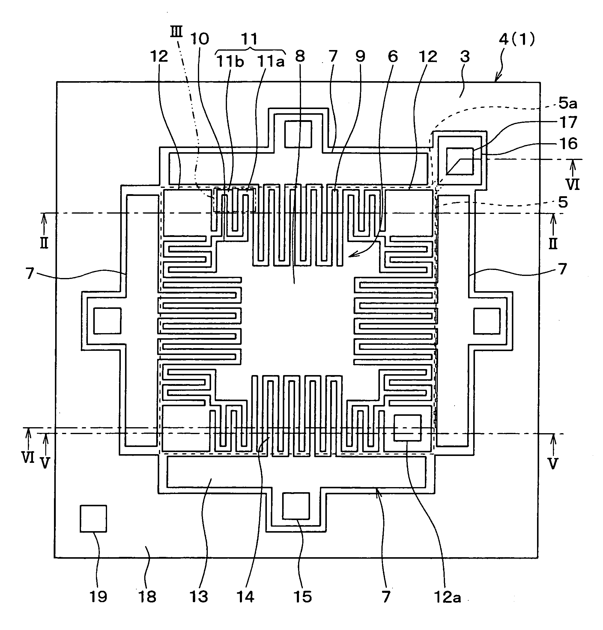
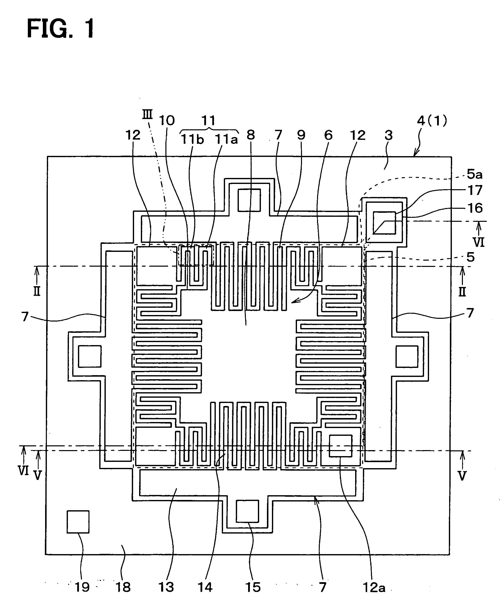
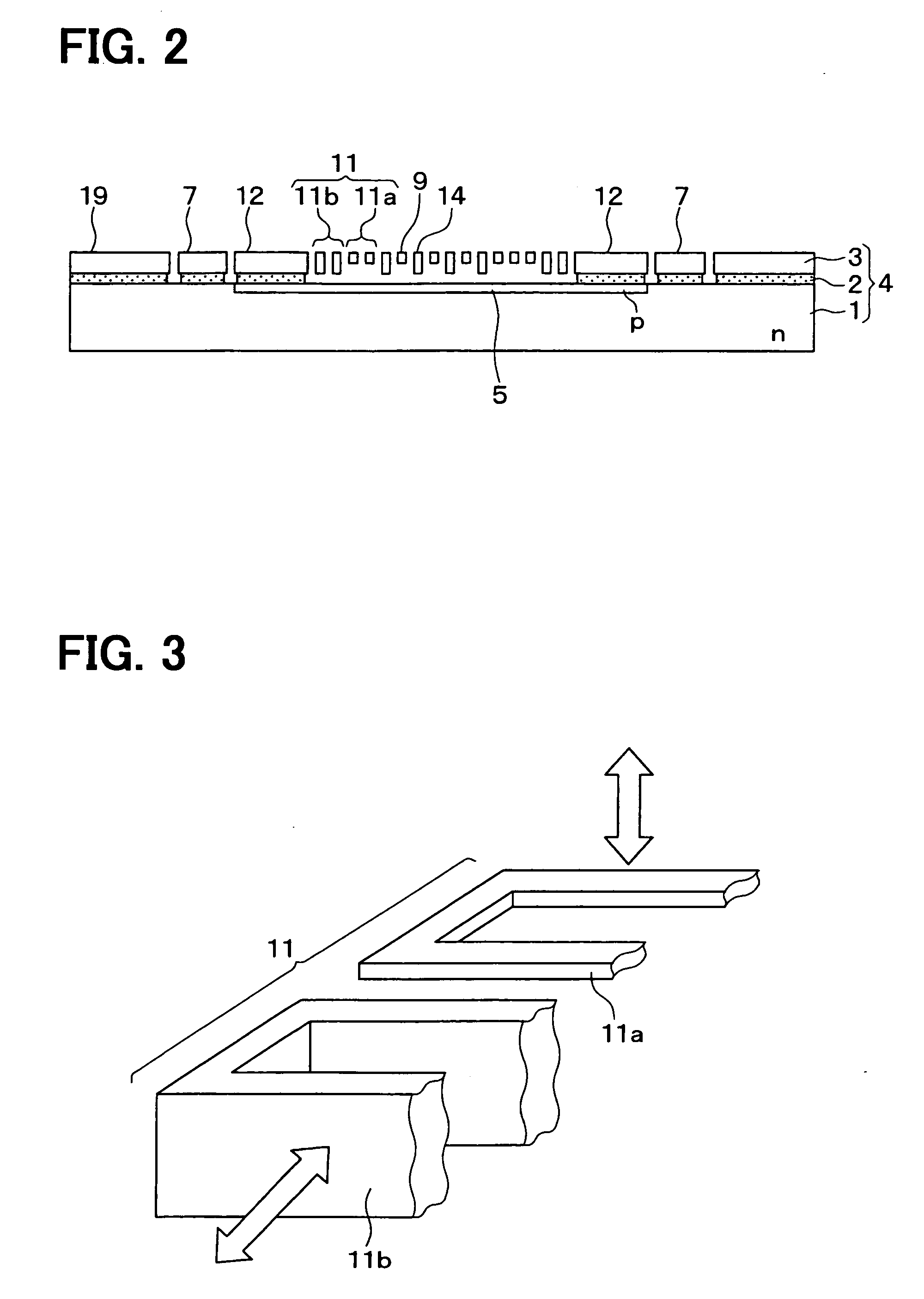
[0046]The following describes a physical sensor according to the first embodiment. The embodiment represents application to a three-axis capacitance-detecting acceleration sensor that detects accelerations in three directions. FIG. 1 is a front view of the acceleration sensor according to the first embodiment. FIG. 2 is a cross sectional view taken along line II-II of FIG. 1. The acceleration sensor according to the embodiment will be described with reference to these drawings.
[0047]As shown in FIGS. 1 and 2, an SOI substrate 4 is used to form a sensor section of the acceleration sensor according to the embodiment. The SOI 4 substrate includes a support substrate 1, an embedded oxide film 2, and a silicon layer 3 that are layered in this order.
[0048]As shown in FIG. 2, the support substrate 1 is made of n-type silicon, for example. A lower electrode 5 doped with p-type impurities is formed over the surface of the support substrate 1 toward the silicon layer 3. The embedded oxide fil...
second embodiment
[0072]The second embodiment will be described below. The acceleration sensor according to the embodiment includes modifications to the first embodiment such as adding a cap and changing the manufacturing method of the acceleration sensor. The basic structure of the acceleration sensor is the same as the first embodiment.
[0073]FIG. 5 is a partially cross sectional perspective view of the acceleration sensor according to the embodiment. FIG. 5 is equivalent to a perspective view based on a cross sectional view taken along line V-V in FIG. 1.
[0074]As shown in FIG. 5, a cap 31 is provided on the surface of the SOI substrate 4. The cap 31 is shaped equally to the SOI substrate 4 and is made of an insulating material such as a non-doped silicon or glass substrate. The cap 31 is bonded to the SOI substrate 4 via the insulating film 32 around the outer edge of the cap 31. The cap 31 functions as a cover for the structures such as the movable section 6 and the fixed section 7 formed on the S...
third embodiment
[0085]The following describes the third embodiment. The acceleration sensor according to the embodiment includes modifications to the first embodiment such as changing the mode of detecting an acceleration in the vertical direction with reference to the substrate and accordingly changing the structure. The basic structure of the acceleration sensor is the same as the first embodiment.
[0086]FIG. 8 is a cross sectional view showing an acceleration sensor according to the third embodiment. FIG. 9 is a partially cross sectional perspective view of the acceleration sensor in FIG. 8. FIG. 9 is equivalent to a perspective view based on a cross sectional view taken along line V-V in FIG. 1.
[0087]As shown in FIG. 8, the acceleration sensor according to the embodiment does not include the lower electrode 5 shown in the first embodiment but includes the upper electrode 30 instead. The upper electrode 30 is shaped equally to the SOI substrate 4 and is arranged on the surface of the cap 31 made ...
PUM
 Abstract
Description
Claims
Application Information
 - R&D
- Intellectual Property
- Life Sciences
- Materials
- Tech Scout
- Unparalleled Data Quality
- Higher Quality Content
- 60% Fewer Hallucinations
Browse by: Latest US Patents, China's latest patents, Technical Efficacy Thesaurus, Application Domain, Technology Topic, Popular Technical Reports.
© 2025 PatSnap. All rights reserved.Legal|Privacy policy|Modern Slavery Act Transparency Statement|Sitemap|About US| Contact US: help@patsnap.com