Combustion chamber of a combustion system

a combustion system and combustion chamber technology, applied in the field of combustion chambers of combustion systems, can solve the problems of not decreasing the efficiency exposing the system to the elements without protection, and forming gaps, so as to ensure the functional capability of the heat shield, ensure the longevity of the combustion system, and prolong the combustion system. the effect of the combustion system

Inactive Publication Date: 2009-08-13
ANSALDO ENERGIA IP UK LTD
View PDF14 Cites 42 Cited by
  • Summary
  • Abstract
  • Description
  • Claims
  • Application Information

AI Technical Summary

Benefits of technology

[0004]For the longevity of the combustion system, the longevity of the heat shield which is arranged in the combustion chamber is important so that the functional capability of the heat shield is ensured. Since modern heat shields customarily comprise a plurality of segments with a plurality of liner elements, gaps are formed between two adjacent liner elements into which a hot gas flow can penetrate. At a bottom of the gap, a support element is often arranged, which on the one hand supports at least one liner element, and on the other hand, in an unfavorable case, is not protected by the liner element against a direct entry contact with the hot gas flow and is therefore exposed to this without protection. Such gaps form potential weak points. In order to ensure the longevity of the combustion system, the gaps between the liner elements should be protected against an excessively large temperature stress.
[0006]The present invention is based on the general idea of locally cooling a gap which is arranged between two liner elements of a heat shield and open towards a combustion space and as a result, effectively protects a support element, which is arranged in the region of a gap bottom against a direct hot gas action. The heat shield, which is provided for temperature protection, has at least two segments, of which each one comprises a liner element, which faces a combustion space, and a retaining device, which fixes the liner element on a support structure via a support element. In this case, each liner element has an edge region, which at the same time forms a wall of a gap. The gap is located between two liner elements and open towards the combustion space. In the region of a gap bottom, a support element is arranged in this case, which closes off the gap on its side and faces away from the combustion space. For cooling the edge regions of the liner elements that face the gap, in this case in at least one edge region of a liner element and / or in the bottom, i.e. for example in the support element, at least one through-opening is provided, through which cooling gas flows into the gap and, as a result, brings about a film cooling of the gap walls which are formed by the two edge regions of the adjacent liner elements. As a result of this, an effective cooling of the gap can be achieved without significantly increasing the oxygen content in the combustion space and consequently without increasing the NOx emissions of the combustion system. It is also conceivable in this case that such a through-opening is provided in only one of the two edge regions of the liner elements, in the two edge regions, only in the gap bottom or at least in one edge region and in the bottom, so that depending upon locally required cooling requirement the cooling can be adapted by different arrangement of the through-openings. As a result of the locally adapted cooling flow, a particularly effective cooling of the gap can be achieved, wherein in gaps with increased cooling requirement more gas is introduced than in gaps with lower cooling requirement. Consequently, the efficiency of the combustion system is not decreased as a result of an excessively intense cooling of the liner elements or of the gaps.
[0007]The edge region of the liner element expediently fits under a flange region, which is formed by the retaining device. This enables a reliable mounting of the liner element on the support element or on the support structure via the retaining device, wherein in comparison to a direct screw fastening temperature expansions can be accommodated in a problem-free manner. Such a mounting of the liner elements thus reduces the risk of excessively high stresses as a result of temperature expansions and therefore contributes to the longevity of the combustion system.
[0008]In an advantageous development of the solution according to the invention, at least the edge regions of the liner elements and / or the support element in the region of the gap bottom have a thermal barrier coating. Such a thermal barrier coating improves the resistance of the liner elements or of the support element to a temperature stress which results from the hot gas flow and consequently increases the service life of the liner elements. The improved resistance of the liner elements or of the support element to a temperature stress, as result of the thermal barrier coating, also reduces a maintenance requirement since the thermal barrier coatings extend the service lives of the liner elements or of the support elements. Extended service lives extend the maintenance intervals, as a result of which the downtimes of the combustion system can be significantly reduced and the combustion system itself can be operated more cost-effectively.

Problems solved by technology

At a bottom of the gap, a support element is often arranged, which on the one hand supports at least one liner element, and on the other hand, in an unfavorable case, is not protected by the liner element against a direct entry contact with the hot gas flow and is therefore exposed to this without protection.
Such gaps form potential weak points.
Consequently, the efficiency of the combustion system is not decreased as a result of an excessively intense cooling of the liner elements or of the gaps.

Method used


Image

  • Combustion chamber of a combustion system
  • Combustion chamber of a combustion system

Examples


Embodiment Construction

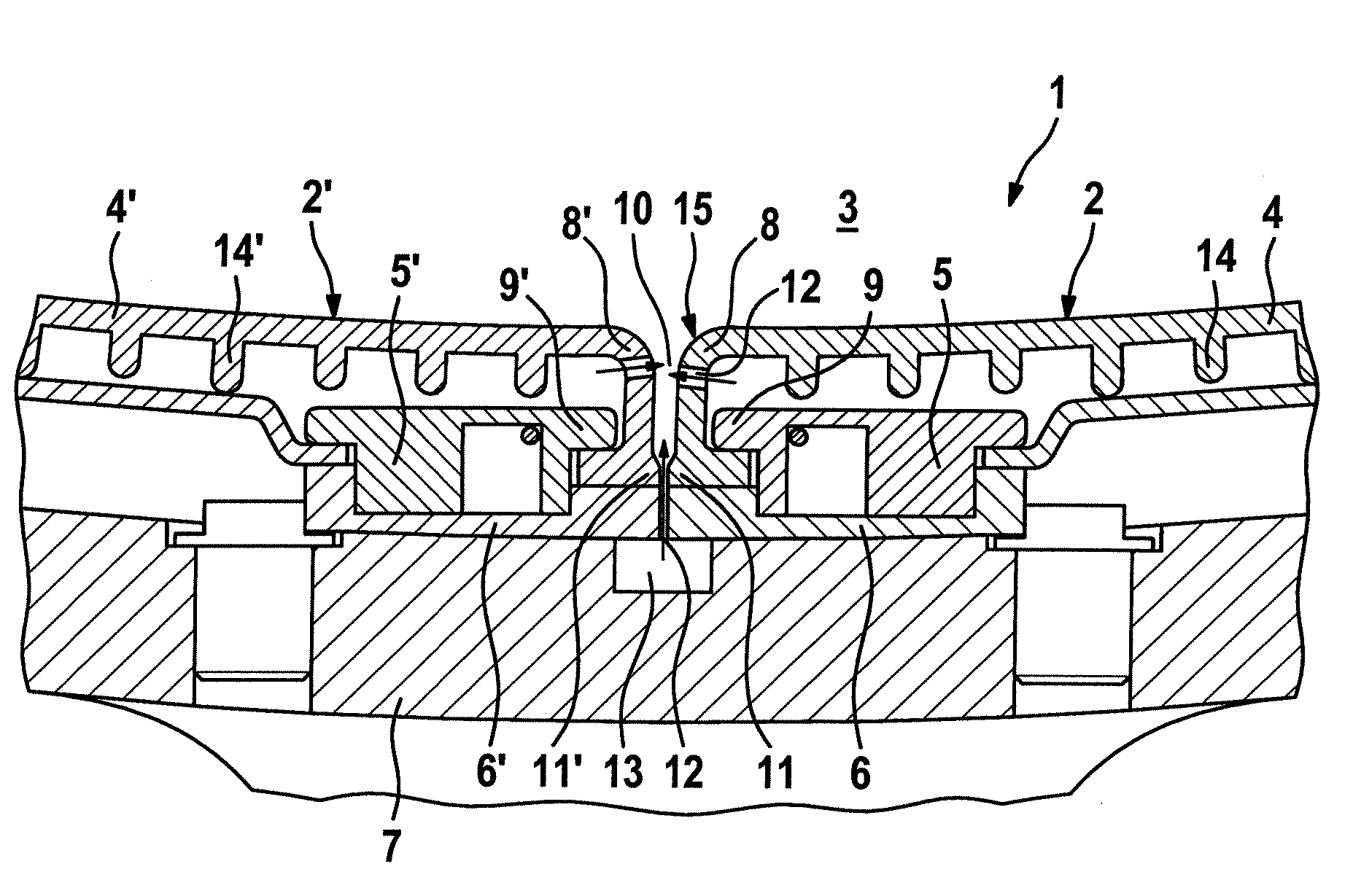
[0014]In accordance with FIG. 1, a sectional view through a combustion chamber wall of a combustion system, especially of a gas turbine, is shown, with a heat shield 1 which has at least two segments 2 and 2′ which are arranged next to each other. The two segments 2, 2′ in each case have a liner element 4 or 4′, which faces a combustion space 3, and a retaining device 5, 5′. The liner element 4 in this case, as well as the liner element 4′, is formed from a material which is not affected by heat so that it withstands in a problem-free manner a direct contact with hot gases which are present in the combustion space 3. The two liner elements 4, 4′ are fixed on a support structure 7 via at least one support element 6, wherein the retaining device 5 fixes both the liner element 4 and the at least one support element 6 on the support structure 7. In this case, fastening of the liner element 4 on the retaining device 5 is carried out by means of an edge region 8 which is formed on the lin...


PUM


Abstract

A combustion chamber of a combustion system comprises a combustion space, a support structure, a heat shield, and at least one through-opening. The heat shield has at least two segments, and each segment has an edge region, a gap communicating with the combustion space being formed between edge regions of adjacent segments, and a retaining device. The adjacent segments include a support element disposed in a bottom region of the gap. The retaining device fixes the respective liner element on the support structure via the respective support element. The at least one through-opening communicates with the gap so as to enable a cooling gas to flow through the through-opening. The at least one through-opening is disposed in at least one of the respective edge region and the support element at the bottom region of the gap.

Description

[0001]This application is a continuation of International Patent Application No. PCT / EP2007 / 056887, filed on Jul. 6, 2007, which claims priority to Swiss Patent Application No. CH 01260 / 06, filed on Aug. 7, 2006. The entire disclosure of both applications is incorporated by reference herein.[0002]The invention refers to a combustion chamber of a combustion system, especially of a gas turbine, with a heat shield which has at least two segments.BACKGROUND[0003]Combustion chambers of a combustion system, for example of a gas turbine, are customarily equipped with a heat shield which protects a subjacent support structure against a direct contact with a hot gas flow. Depending upon position in the combustion chamber, or with regard to the hot gas flow, the heat shield, or individual segments of it, in this case is or are exposed to a variable temperature stress.SUMMARY OF THE INVENTION[0004]For the longevity of the combustion system, the longevity of the heat shield which is arranged in...

Claims


Application Information

Patent Timeline
Patent Type & Authority Applications(United States)
IPC IPC(8): F23M5/00
CPCF23R3/002F23M5/08
Inventor TSCHIRREN, STEFANBURRI, DANIELABDON, ANDREASSTEINBACH, CHRISTIAN
Owner ANSALDO ENERGIA IP UK LTD
Why Eureka
Try Eureka