Orbital hybrid magnetic electronic engine and generator

a hybrid magnetic and electronic engine technology, applied in the direction of mechanical energy handling, magnetic circuit rotating parts, magnetic circuit shape/form/construction, etc., can solve the problems of excessive heat, energy consumption, and reducing the life of the motor, and achieve the effect of reducing energy consumption

Inactive Publication Date: 2009-08-13
BERDUT TERUEL ELBERTO
View PDF11 Cites 12 Cited by
  • Summary
  • Abstract
  • Description
  • Claims
  • Application Information

AI Technical Summary

Benefits of technology

[0008]The present invention overcomes the disadvantages of the Prior Art and provides a configuration between the rotor and the commutation system wherein the energy consumption is reduced.
[0009]Another object of the invention is to provide a configuration that reduces heat and increases motor life.

Problems solved by technology

However, the consumption of energy and the excessive heat at the coil structure is still a major problem producing demagnetization and reducing motor life.

Method used


Image

  • Orbital hybrid magnetic electronic engine and generator
  • Orbital hybrid magnetic electronic engine and generator
  • Orbital hybrid magnetic electronic engine and generator

Examples


Embodiment Construction

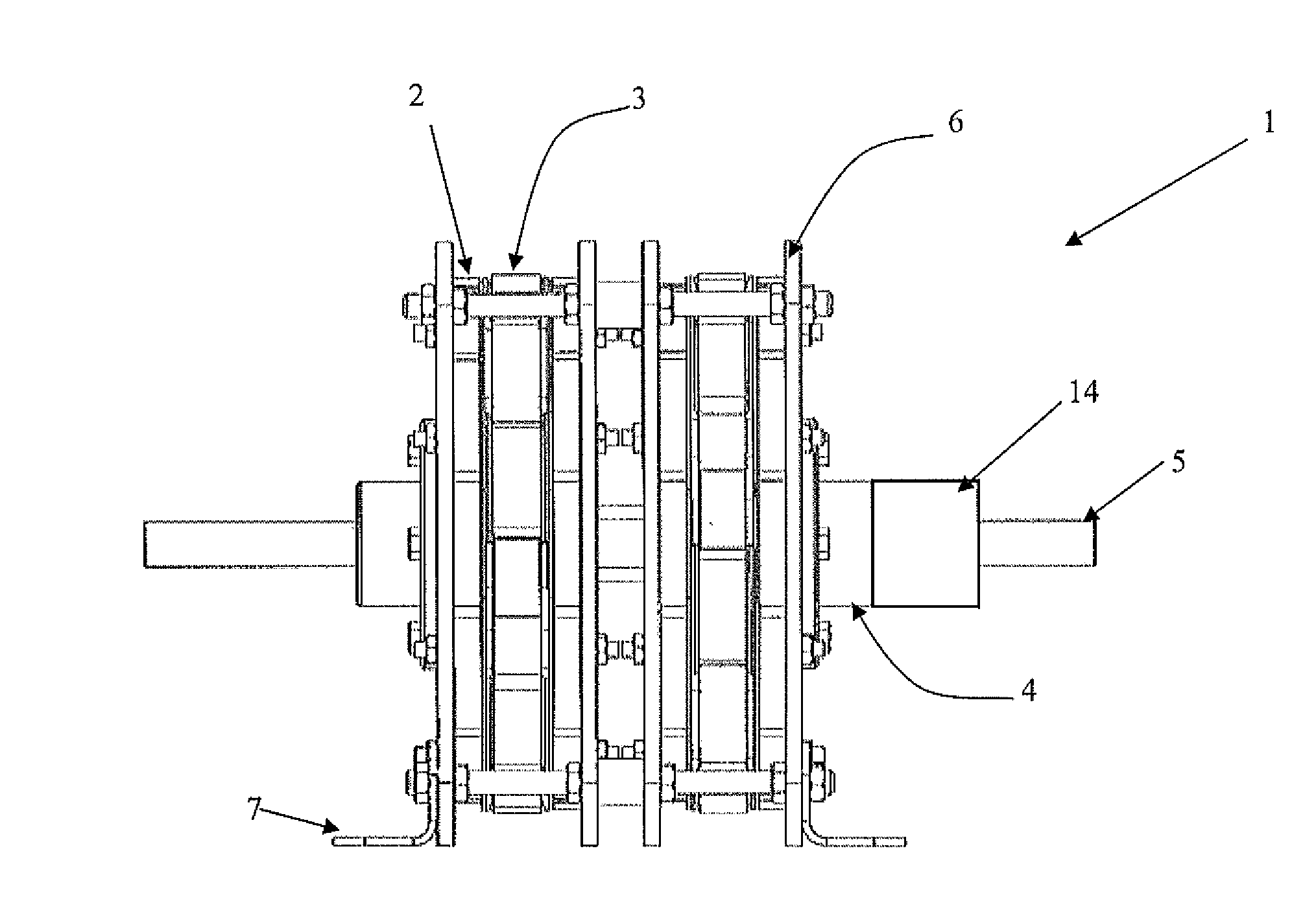
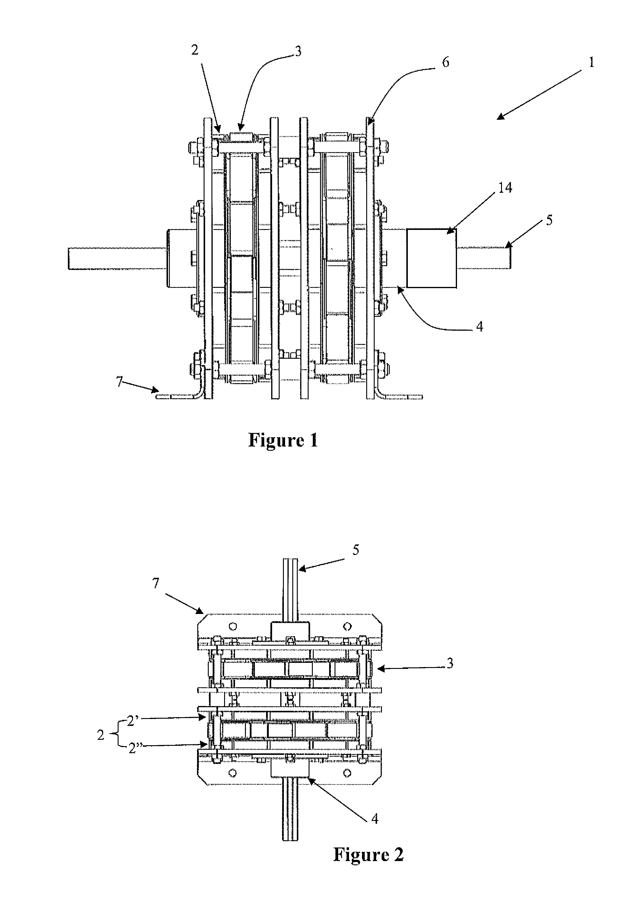
[0047]FIGS. 1 to 3 show a DC motor 1 as an example for the present invention. The DC motor 1 comprises a stator 2 with permanent magnets 8, a rotor 3 with coils 11 (FIGS. 14-15), bearings 4, a shaft 5, a frame 6 and a commutation system 14. The DC motor 1 is a flat motor having two motors connected in parallel to the same shaft 5. The stator is assembled to the frame 6 by connecting means such as bolts or any other mean that fixes the stator structure to the frame. The stabilization and support of the frame to any other structure is acquired by adding position holders 7 to each side of the frame 6. Bearings are provided at the distal ends of the shaft and are connected and fixed to the frame 6 by bolts.

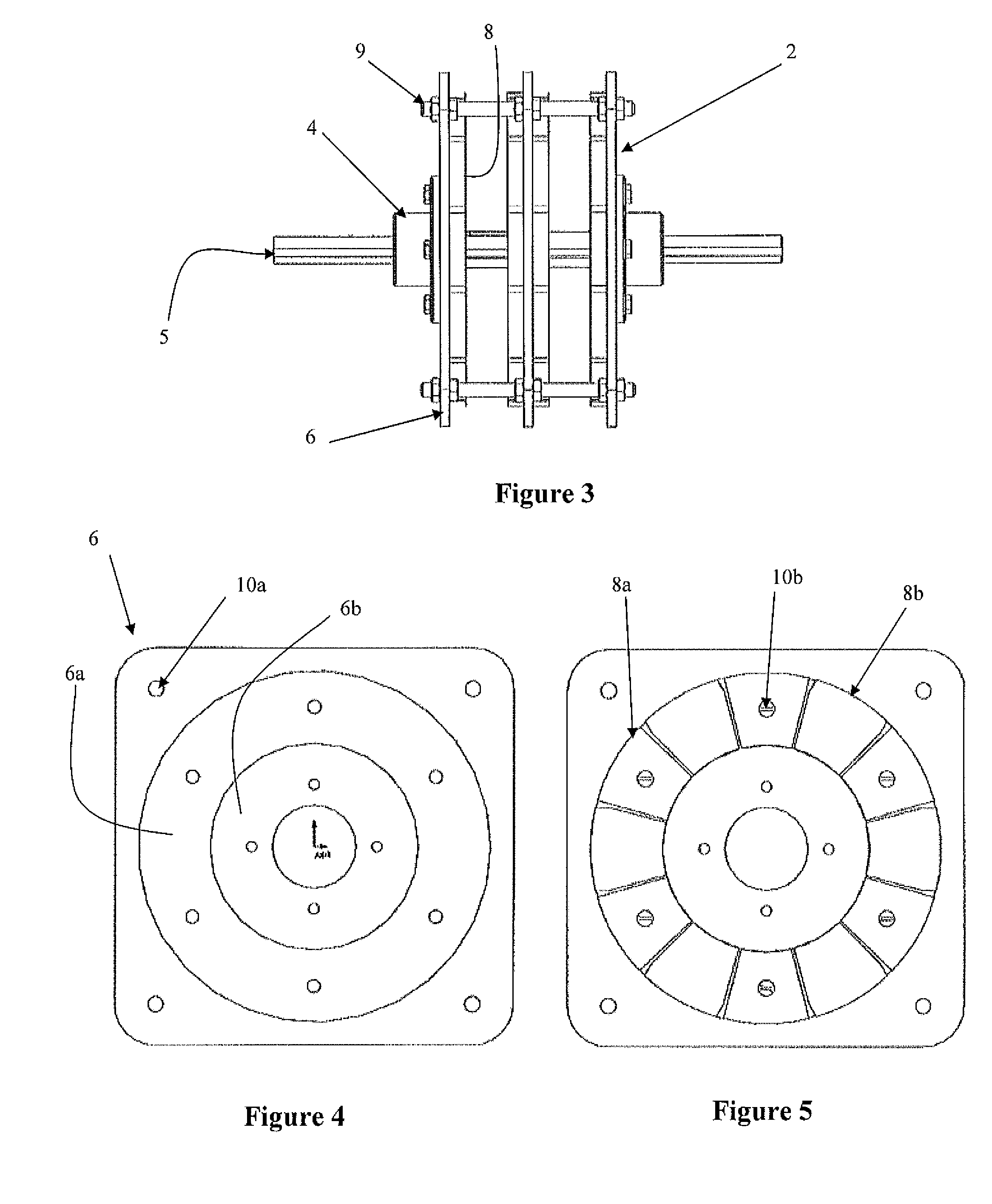
[0048]The stator 2, as mentioned before, comprises several magnets 8 arranged in a circular contour, wherein two stator similar parts 2′, 2″ parallel to each other are facing the rotor which is located between both stator parts. FIGS. 3-7 show the stator assembly 2 with the shaft 5. M...


PUM


Abstract

A motor configuration between the rotor and the commutation system, comprising rotor coils energized by mechanical or electrical ways wherein a positive charge, negative charge and a no-charge section is applied in order to reduce the heat and energy consumption and therefore increasing the motor life.

Description

STATEMENT REGARDING FEDERALLY SPONSORED RESEARCH AND DEVELOPMENT[0001]N / ARELATED APPLICATIONS[0002]N / ABACKGROUND OF THE INVENTION[0003]1. Field of the Invention[0004]The invention is related to a motor and configuration between the rotor and the commutation system, and more specifically a motor wherein said rotor is aligned with the commutation system providing less energy consumption reducing heat damages at the coils.[0005]2. Discussion of the Background[0006]Motors are used for several applications in our daily life. Basically, the motor structure comprises a rotor and a stator wherein said stator and / or rotor are either made by wound coils or permanent magnets. The interaction between a magnetic field and electric field generates the rotational or linear motion for the motor. The DC motor, for example, is a type of motor which runs by DC electric power. Most common DC motors are brushed and brushless types.[0007]Throughout the years many improvements have been implemented to eli...

Claims


Application Information

Patent Timeline
Patent Type & Authority Applications(United States)
IPC IPC(8): H02K16/00H02K7/08H02K1/17
CPCH02K1/24H02K1/30H02K23/54H02K21/26H02K23/04H02K16/00
Inventor BERDUT-TERUEL, ELBERTO
Owner BERDUT TERUEL ELBERTO
Why Eureka
Try Eureka