
System and method for controlling four-quadrant operation of a switched reluctance motor drive through a single controllable switch

a two-phase switched reluctance machine and control system technology, applied in the direction of electronic commutation motor control, motor/generator/converter stopper, dynamo-electric converter control, etc., can solve the problems of circuit requiring one controllable and one uncontrollable power device, and no control method for reversing the rotor rotation of the machin

Active Publication Date: 2009-08-13
REGAL BELOIT AMERICA +1
View PDF8 Cites 19 Cited by
  • Summary
  • Abstract
  • Description
  • Claims
  • Application Information

AI Technical Summary

Benefits of technology

The present invention provides a method and system for controlling the speed of a two-phase switched reluctance machine (TPSRM) rotor using a power converter with only one controllable switch. This allows for speed control during both the motoring mode and braking mode of operation, and the recovery of mechanical energy from the machine's inertia and load to produce a braking effect. The system includes a speed control feedback loop and a current control feedback loop, which dynamically adjust a first and second parameter to produce the control signal. The method also includes a method of reversing the rotational direction of the TPSRM rotor. The technical effects of the invention include improved speed control, better energy utilization, and improved braking performance.

Problems solved by technology

If such independent control of individual phase excitation is not possible, there is no control method that can reverse the machine's rotor rotation from one direction to another.
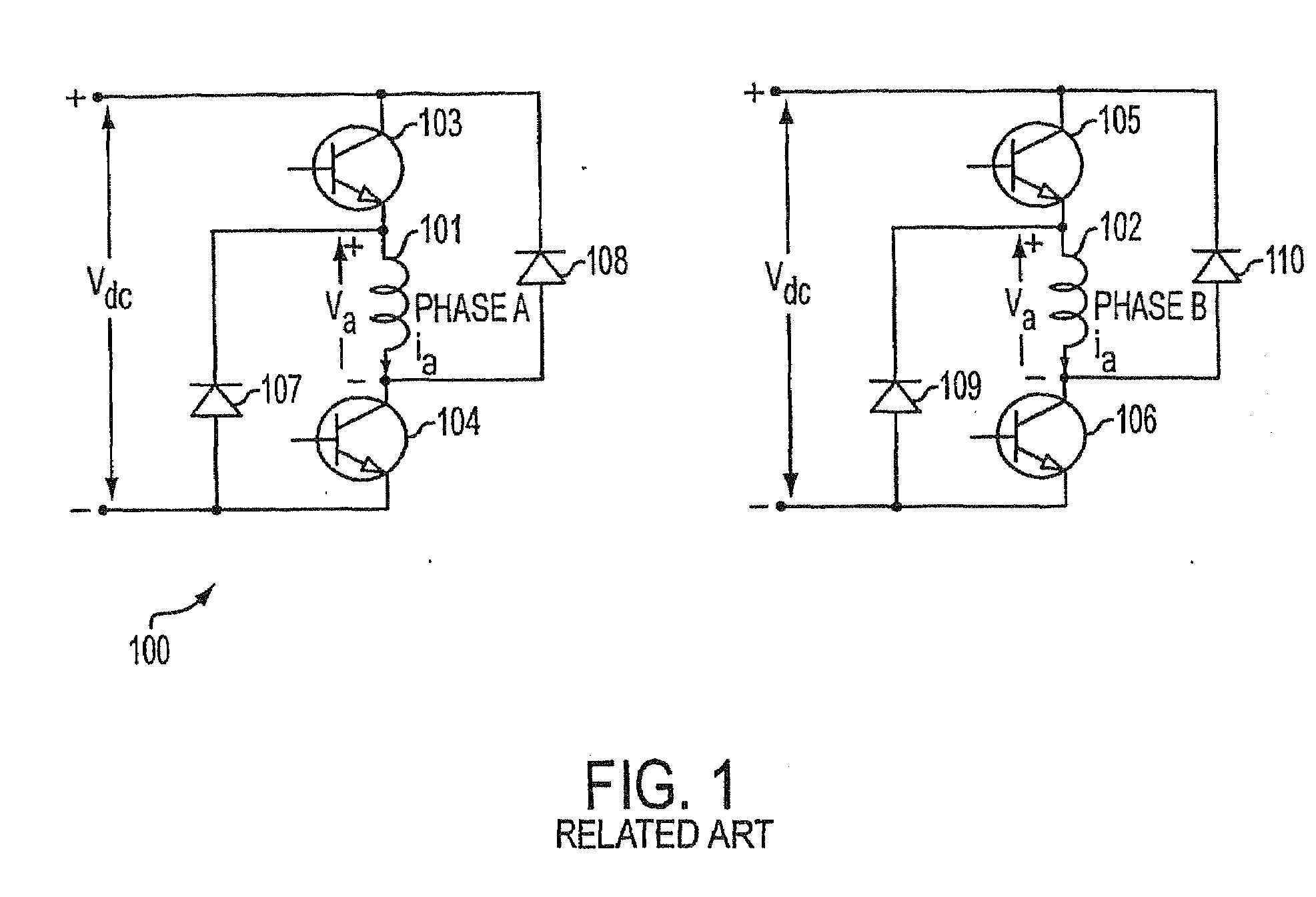
The disadvantage of this power converter topology is that it uses eight power devices.
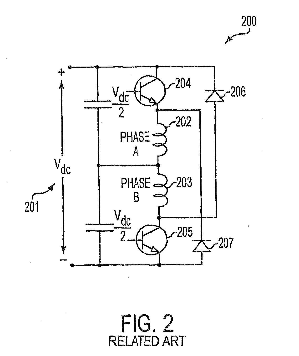
This results in a circuit requiring one controllable and one uncontrollable power device per phase winding 202, 203.
The disadvantage of this circuit is that it reduces the available dc source voltage by half and, therefore, doubles the current rating required for the devices and for the machine, resulting in low efficiency machine operation.
These are severe limitations.
Moreover, these topologies do not provide for a common emitter connection of the switches, thereby creating an isolation requirement for the gate drive circuits and a higher cost for the additional components.
As a result of the above-mention and other factors, these circuits are strongly limited to low cost variable speed applications.
Use of external inductor 310 increases the cost, whereas the use of the power resistor (not shown) will result in a lower efficiency of the system and higher package volume, due to increased thermal considerations.
Therefore, this circuit is not ideal for use with two-phase SRMs.
This special winding increases the copper volume in the machine windings, resulting in increased cost for the machine.
This leakage inductance can be minimized but cannot be eliminated in a practical machine.
Circuits requiring only two controllable switches and two diodes have the disadvantages of high power loss, low efficiency, and a bifilar winding in the machine, thereby reducing the power density of the machine.
Therefore, existing solutions are not attractive with regard to considerations of high efficiency operation, full range of speed control, compactness in the converter's packaging and, most importantly of all, the overall cost of the system.
A fundamental challenge in power converter development has been to reduce the number of power devices, both controllable and uncontrollable, to a level corresponding to that of a single-quadrant chopper drive, such as is commonly used in a dc motor drive or in a universal motor drive.

Method used


Image

  • System and method for controlling four-quadrant operation of a switched reluctance motor drive through a single controllable switch
  • System and method for controlling four-quadrant operation of a switched reluctance motor drive through a single controllable switch
  • System and method for controlling four-quadrant operation of a switched reluctance motor drive through a single controllable switch

Examples


Embodiment Construction

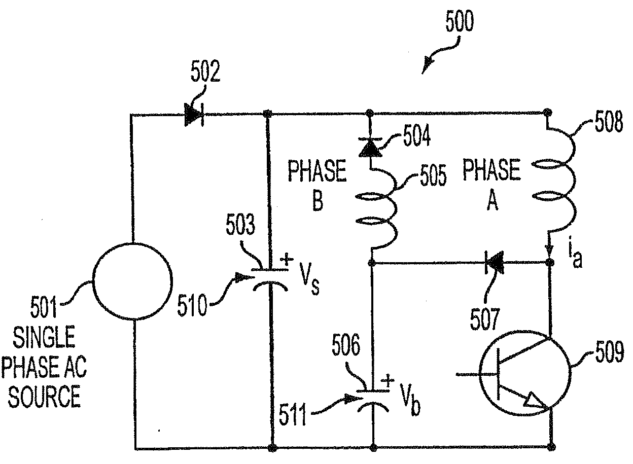
[0045]FIG. 5 illustrates a single-switch power controller in the form of a power converter 500 for driving a two-phase switched reluctance machine (SRM). One winding of the SRM is alternatively referred to as a main or phase A winding 508, while the other winding is referred to as an auxiliary or phase B winding 505. Although phase windings 505, 508 of the SRM may be spatially separated from power converter 500 and may also be considered to form a part of the machine (also referred to herein as a motor) rather than part of the power converter, these windings 505, 508 are illustrated in the power converter circuit for the purpose of simplifying the description of their cooperative functionality with power converter 500.

[0046]When power converter 500 is activated by the application of an alternating current (ac) source voltage 501, a dc source 510 comes into effect through the rectification and filtering provided by a diode 502 and a dc source capacitor 503, respectively. As dc source...


PUM


Abstract

A single controllable switch (509) drive system for regulating the speed of a two-phase switched reluctance machine (TPSRM) (700) rotor may include a speed control feedback loop (970) component that uses an established speed control signal and a signal indicative of the rotor's speed to dynamically adjust a first parameter. And a current control feedback loop (976) component that uses an established current control signal and a signal indicative of the current flowing through a stator winding (505,508) of the TPSRM to dynamically adjust a second parameter.

Description

CROSS-REFERENCE TO RELATED APPLICATIONS[0001]This application claims priority to U.S. Provisional Application No. 60 / 614,547 and incorporates by reference this provisional application in its entirety. Additionally, the application incorporates by reference the disclosures provided in Applicant's co-pending PCT International Application Nos. PCT / US03 / 16627, PCT / US03 / 16628, PCT / US03 / 16629, PCT / US03 / 16630, and PCT / US03 / 16631.FIELD OF THE INVENTION[0002]The present invention relates to a method and system for controlling the operation of a two-phase switched reluctance machine (TPSRM). More specifically, the invention relates to controlling the TPSRM with a power converter employing a single controllable switch.BACKGROUND OF THE RELATED ART[0003]A two-phase switched reluctance machine (TPSRM) is a switched reluctance machine (SRM) with two phases, phases A and B. displaced from each other by 180 degrees / n, where n is the number of stator poles per phase. FIGS. 7(a) and 7(b) illustrate a...

Claims


Application Information

Patent Timeline
Patent Type & Authority Applications(United States)
IPC IPC(8): H02P6/08
CPCH02P25/085H02P25/092
Inventor RAMU, KRISHNANHA, KEUNSOOPARK, SUNG-YEUL
Owner REGAL BELOIT AMERICA
Learn More