
Traveling Lane Detector

a detector and lane technology, applied in the field of traveling lane detectors, can solve the problems of inability to extract the edge parts of both inability to detect the edge parts of the lane mark, and inability to satisfy the extraction of the edge parts of the left and right lane marks, so as to speed up image processing and reduce erroneous detection

Inactive Publication Date: 2009-08-13
HITACHI LTD
View PDF16 Cites 14 Cited by
  • Summary
  • Abstract
  • Description
  • Claims
  • Application Information

AI Technical Summary

Benefits of technology

[0012]An object of the present invention is to provide a traveling lane detector that is capable of detecting a lane mark accurately and stably by simple processing even when a vehicle is crossing the lane mark.
[0018]The traveling lane detector according to the present invention is capable of detecting lane marks stably even when the vehicle is crossing a lane mark and hence reducing erroneous detection. In addition, since the traveling lane detector employs such simple window setting, speedup in image processing can be expected with this traveling lane detector.

Problems solved by technology

When the edge detection threshold is set too high, edge parts of the lane mark cannot be detected.
When the edge detection threshold is set too low, on the other hand, a number of parts that have nothing to do with the lane mark, such as the boundary of a shadow and dirt on the road surface, are extracted, resulting in erroneous detection.
Accordingly, in the above case, if only a single threshold is used, satisfactory extraction of edge parts of both the left and right lane marks is not possible because optimal edge detection thresholds for the left and right lane marks are different.
However, when the left and right lane marks is detected from two simply-divided images, the following problem arises.
Once track of the lane mark is lost, it takes time to accurately detect the lane again, and vehicle control using results of traveling lane detection is not possible in the meantime.
For this reason, once a noise part, which is not a lane mark, is detected erroneously as the lane mark, the erroneous detection of the noise part may continue for a while.
In addition, since windows used for detection have a more complicated shape than a rectangle, or a large number of windows are used, it is difficult to speed up processing by using parallel processing.

Method used


Image

  • Traveling Lane Detector
  • Traveling Lane Detector
  • Traveling Lane Detector

Examples


Embodiment Construction

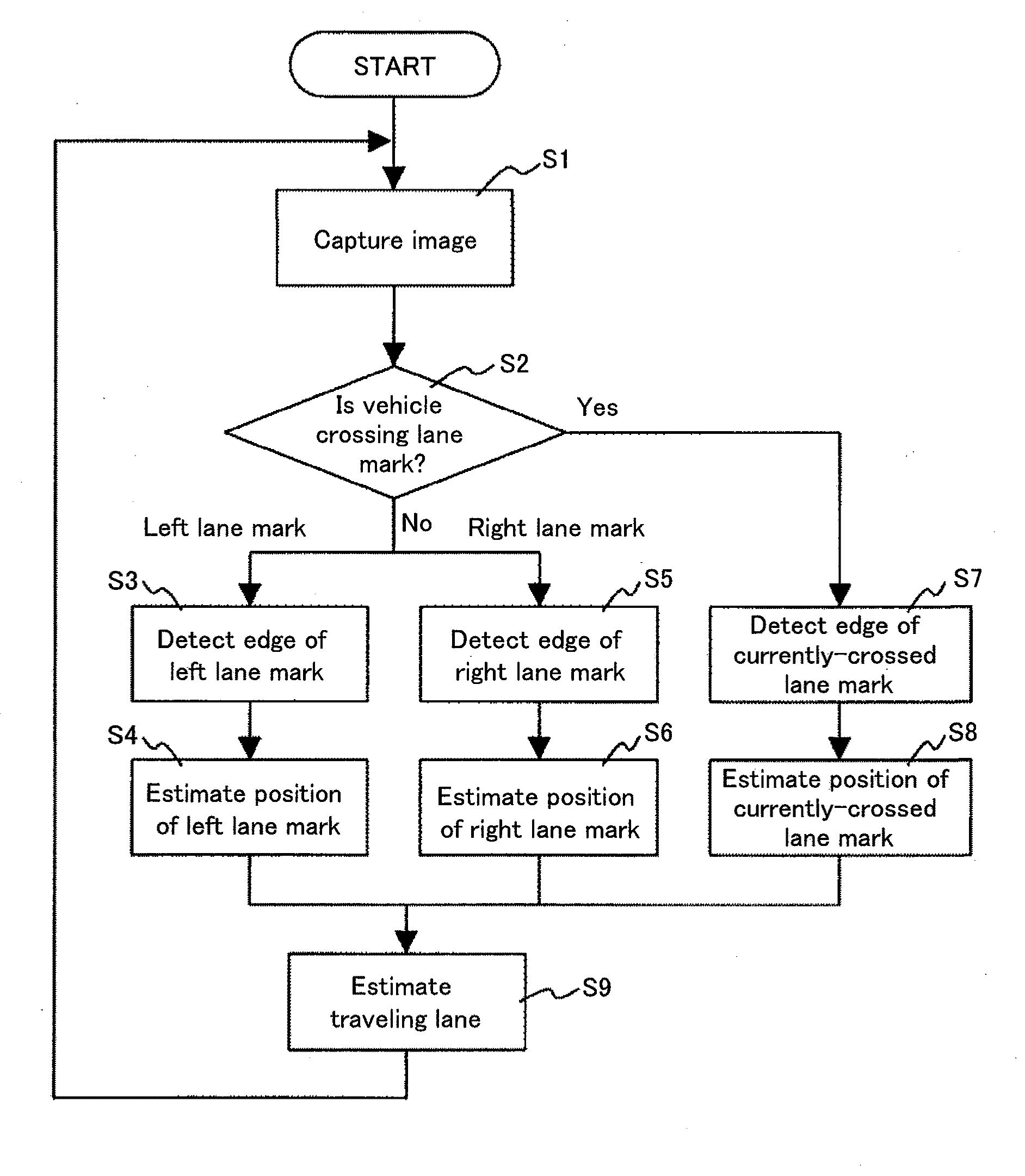
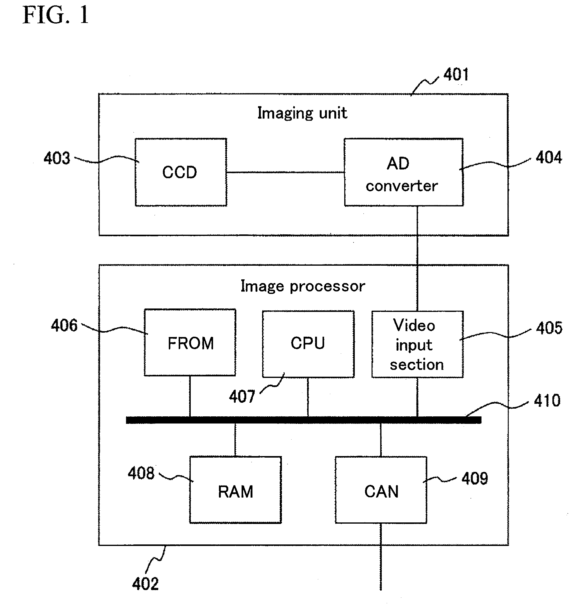
[0026]FIG. 1 is a functional block diagram showing an example of a configuration of a traveling lane detector according to an embodiment of the present invention. The traveling lane according to this embodiment includes two main units, an imaging unit 401 and an image processor 402. The imaging unit 401 includes a charge-coupled device image sensor (referred to as a CCD, below) 403 and an AD converter 404. The image processor 402 includes a video input section 405, a flash ROM (FROM) (non-volatile memory) 406, a central processing unit (CPU) 407, a random access memory (RAM) 408 and a control area network (CAN) 409. The imaging unit 401 is mounted on a vehicle in such a position that the CCD 403 can capture a road surface in front of or behind the vehicle so as to take an image of lane marks. A single or multiple windows are defined in a taken image as described below, thereby performing lane mark detection processing using image processing.

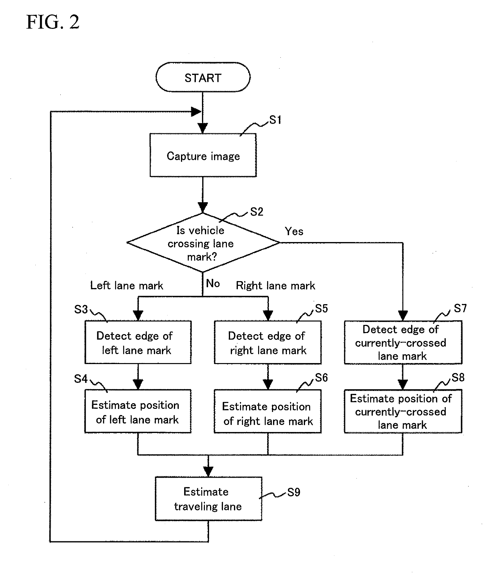
[0027]FIG. 2 is a flowchart of processing ...


PUM


Abstract

A traveling lane detector according to the present invention includes: an imaging unit mounted on a vehicle to take a road surface image; and an image processor performing image processing on the image to detect lane marks on the road surface. The image processor judges whether the vehicle is crossing the lane marks, and, when the vehicle is not crossing any of the lane marks, defines first and second windows, in the image, for detecting the lane marks located respectively on left and right parts of a road surface in front of or behind the vehicle, performs image processing on the image in each of the windows to detect the lane marks, and, when the vehicle is crossing any of the lane marks, defines a third window including the currently-crossed lane mark in the image, performs image processing on the image in the third window to detect the lane mark.

Description

BACKGROUND OF THE INVENTION[0001]1. Field of the Invention[0002]The present invention relates to a traveling lane detector used for detecting a lane on which a vehicle is traveling.[0003]2. Description of the Related Art[0004]Various techniques have been conventionally proposed for a traveling lane detector mounted on a vehicle such as an automobile. In these techniques, lane marks such as a white line drawn on a road are detected through image processing, and when the detection result reveals that the vehicle is out of the traveling lane, warning is issued to the driver, or the steering is controlled, for example.[0005]Such lane mark detection generally uses a luminance difference between a lane mark and a road surface. A luminance difference between a lane mark and a road surface is clearly observed in an image taken from a vehicle, and a part that has a large luminance difference is called an edge. An edge corresponds to a boundary between the lane mark and the road surface, i.e....

Claims


Application Information

Patent Timeline
IPC IPC(8): H04N7/18G06V10/25
CPCG06K9/3233G06K9/00798G05D1/0246G06V20/588G06V10/25
Inventor OTSUKA, YUJITAKEMURA, MASAYUKIMONJI, TATSUHIKOFURUSAWA, ISAO
Owner HITACHI LTD
Learn More