
High efficiency LED light source arrangement

a led light source and high efficiency technology, applied in the field of light sources, can solve the problems of low efficiency in the ratio of input power to leds and white light power output from the arrangement, and achieve the effects of increasing efficiency, enhancing color homogeneity of output light, and reducing loss of color homogeneity

Inactive Publication Date: 2009-08-13
KONINKLIJKE PHILIPS ELECTRONICS NV
View PDF8 Cites 62 Cited by
  • Summary
  • Abstract
  • Description
  • Claims
  • Application Information

AI Technical Summary

Benefits of technology

The present invention is about improving the efficiency of a LED light source that produces a light beam of any color. The invention includes a lighting system that includes a collimator and a second optical element. The collimator has a plurality of light sources that emit light of different colors. The collimator has an entry aperture and an exit aperture. The collimator emits light in a way that provides color homogenization and collimated light. The second optical element further collimates the light and provides a more uniform beam. The cross-sectional area of the exit aperture of the collimator is larger than the cross-sectional area of the entry aperture. The collimator and second optical element may be made of a transparent dielectric material with elongated prism structures. The invention improves the efficiency of LED light sources and provides better color control in lighting systems.

Problems solved by technology

However, the arrangement in US 2002 / 0080622 A1 does not have a high efficiency in terms of the ratio of input power to the LEDs and the white light power output from the arrangement.

Method used


Image

  • High efficiency LED light source arrangement
  • High efficiency LED light source arrangement
  • High efficiency LED light source arrangement

Examples


Embodiment Construction

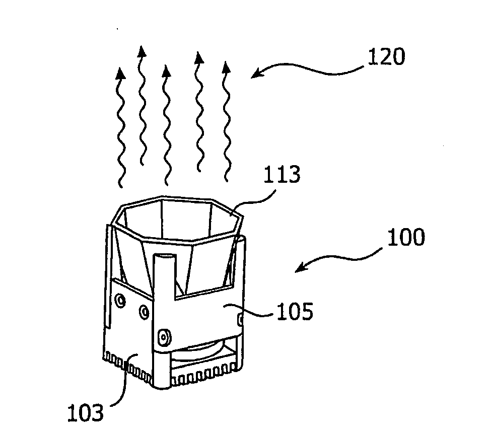
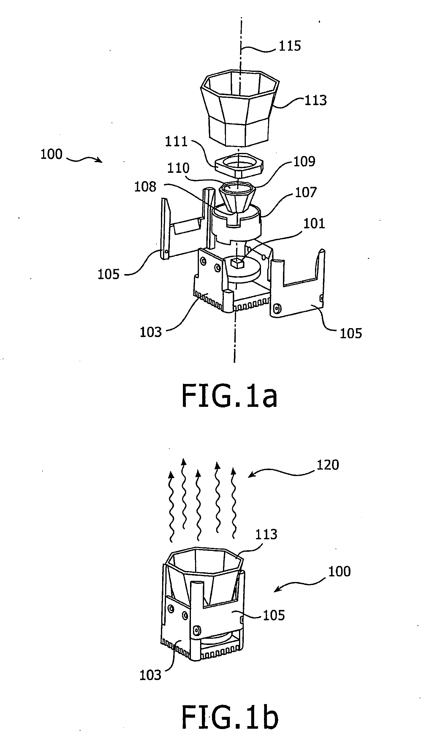
[0037]With reference to FIG. 1a, a lighting system 100 according to a preferred embodiment of the present invention comprises light sources in the form of an array of light emitting diodes (LED) 101 arranged on a base 103 and concentrically arranged around an optical axis 115. Means for providing electric power as well as control signals to the LED's are needed. Additionally, optical and / or thermal sensors can be applied to provide feed back signals to the driver and / or control electronics. However, as the skilled person will realize, these are not shown in FIG. 1a for the sake of simplicity. Protecting side walls 105 are configured to be attached to the base 103 that also contribute to the heat transfer.

[0038]Concentric with the optical axis 115 are a number of optical components arranged as follows. A cylindrical tube 107 is configured to enclose a dielectric collimator 109 having surfaces that achieve total internal reflection (TIR) of the light emitted from the LED array. The co...


PUM


Abstract

A light source (100) comprises a number of optical components aligned concentrically along an optical axis (115). The optical components include an array of light emitting diodes (101), a dielectric collimator (109) having surfaces configured to provide total internal reflection of light emitted from the array of diodes, and a second stage reflector (113) to further collimate the beam and which also may be based on total internal reflection by a prism structure on the outside.

Description

TECHNICAL FIELD[0001]The present invention relates to a light source comprising light emitting diodes and reflecting optical components.BACKGROUND[0002]Light emitting diodes (LED) are used in many ways to create light having almost any color. One way of obtaining a beam of mixed color light is to direct a plurality of individual beams of light, each beam consisting of light emitted from LEDs of a single wavelength, onto a target, whereby the mixed light is obtained at the target. Another way of obtaining mixed light, using LEDs, is to co-locate LEDs having different wavelength characteristics and mixing the light from the LEDs by way of a diffuser.[0003]Yet another way of obtaining mixed light, using LEDs, is to provide a collimating reflector in contact via a transparent dielectric with the LEDs, as disclosed in US patent Application Publication 2002 / 0080622 A1. There, a light source including a LED array being embedded in a dielectric filler produces white light via a tubular refl...

Claims


Application Information

Patent Timeline
Patent Type & Authority Applications(United States)
IPC IPC(8): F21V9/00
CPCF21S10/02F21V7/0091H01L33/60F21Y2101/02G02B5/09F21V13/04F21Y2115/10F21V7/04F21V7/00
Inventor HOELEN, CHRISTOPH GERARD AUGUSTANSEMS, JOHANNES PETRUS MARIA
Owner KONINKLIJKE PHILIPS ELECTRONICS NV
Learn More