Wireless x-ray fluoroscopic imaging system, inter-unit synchronization method of the same, and computer program

a fluoroscopic imaging and synchronization method technology, applied in the field of xray fluoroscopic imaging system, can solve the problems of difficult to establish synchronization, power supply and large-volume image data handling, and inability to read accurate image data ou

Inactive Publication Date: 2009-08-13
CANON KK
View PDF3 Cites 24 Cited by
  • Summary
  • Abstract
  • Description
  • Claims
  • Application Information

AI Technical Summary

Problems solved by technology

Therefore, no accurate image data can be read out if the next X-ray exposure is started before readout is completed.
To make the sensor unit 110 wireless, how to handle the power supply and large-volume image data is a problem.
However, the largest problem is how to wirelessly synchronize the sensor unit 110 and X-ray generation unit 130 as described above.
However, it is difficult to establish synchronization by defining a dedicated packet on a communication protocol of, for example, a wireless LAN.
A delay oc

Method used


Image

  • Wireless x-ray fluoroscopic imaging system, inter-unit synchronization method of the same, and computer program
  • Wireless x-ray fluoroscopic imaging system, inter-unit synchronization method of the same, and computer program
  • Wireless x-ray fluoroscopic imaging system, inter-unit synchronization method of the same, and computer program

Examples


first embodiment

[0047]An outline of this embodiment will be explained below with reference to FIG. 6. FIG. 6 is an example of a system block diagram for explaining the outline of the first embodiment of the present invention.

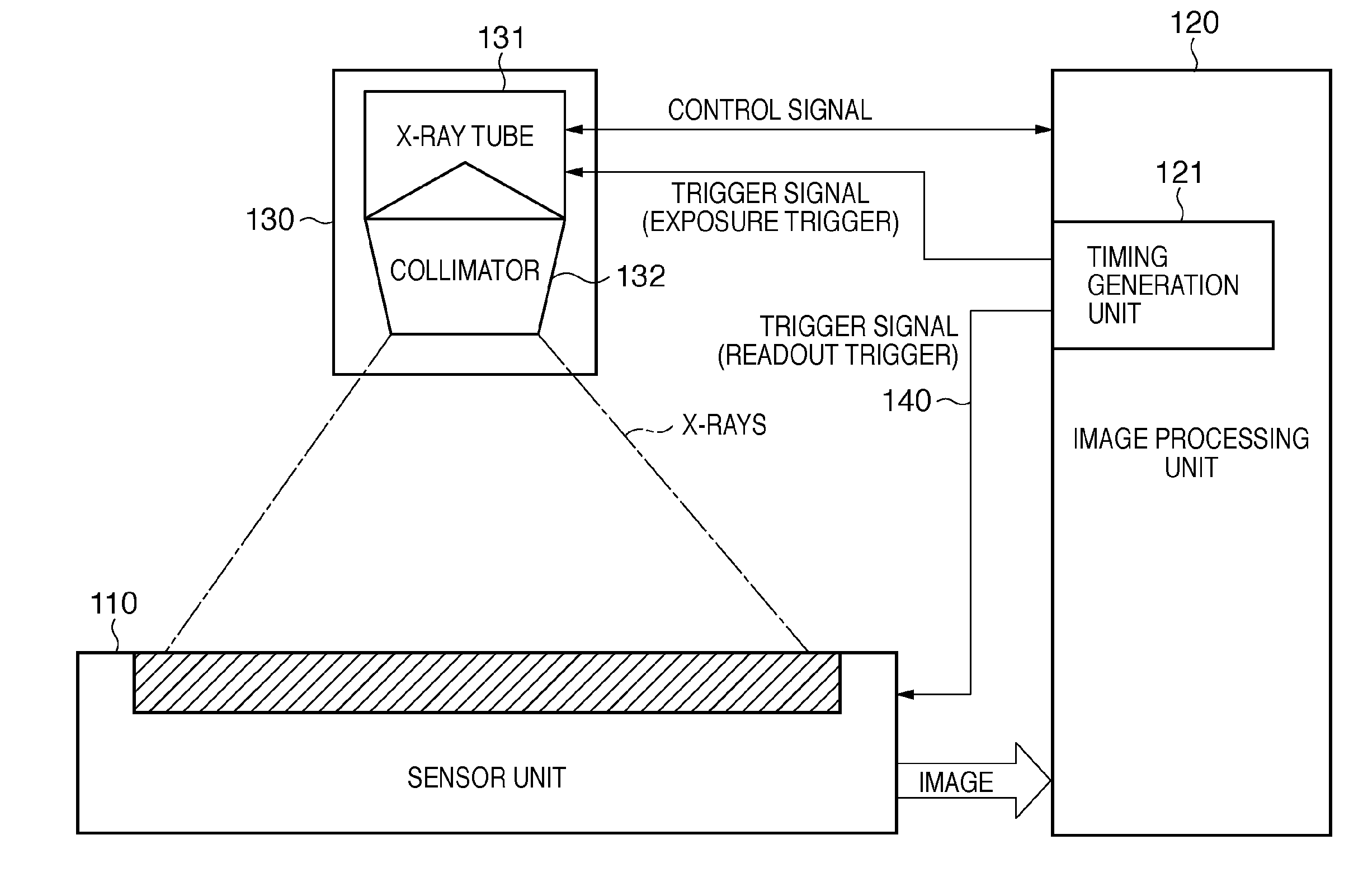
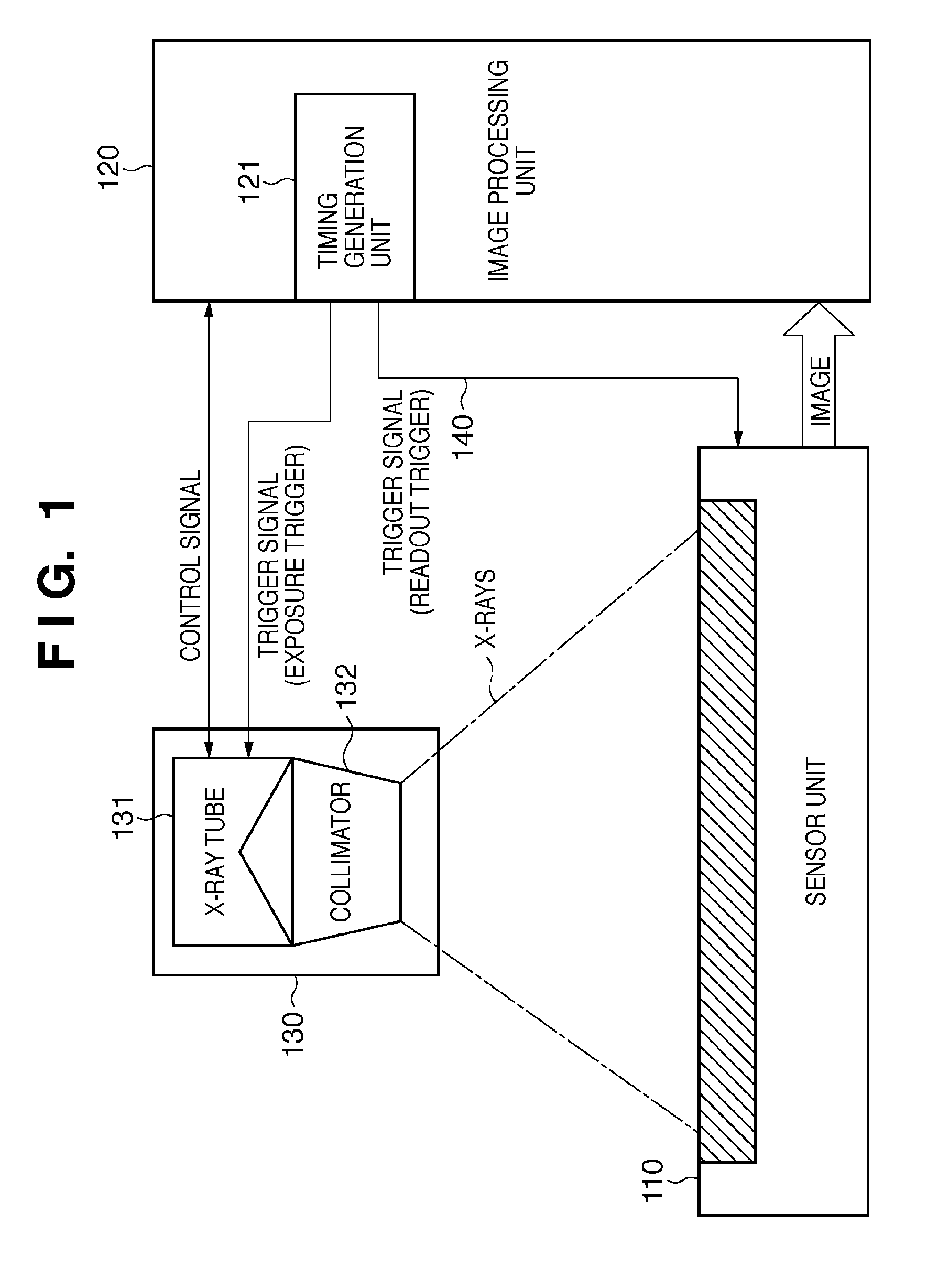
[0048]An X-ray fluoroscopic imaging system according to the present invention includes a sensor unit 610 physically separated from other units, and an image processing unit 620 including an X-ray generation unit 630 required operating in synchronism with the sensor unit 610.

[0049]The sensor unit 610 has a wireless communication unit A 611 and compare timer A 612. The compare time A 612 generates a readout trigger. This readout trigger initiates readout from the sensor.

[0050]The image processing unit 620 includes a wireless communication unit B 621, compare timer B 622, and timing generation unit 623. The compare timer B 622 generates an exposure trigger for an X-ray tube 631. This exposure trigger initiates X-ray exposure. The timing generation unit 623 generates a timing signa...

second embodiment

[0085]In the first embodiment, the method of synchronizing the timings of the wirelessly connected sensor unit and image processing unit by using the beacon signal synchronized with the frame cycle has been described. In the second embodiment, an application form of the present invention when performing angiography or the like by which fluoroscopic imaging is performed while changing the frame cycle will be described.

[0086]To explain an outline of this embodiment, the case where the first frame cycle is changed to the second frame cycle will be explained. Assume that fluoroscopic imaging is performed by the first readout trigger offset and first exposure trigger offset for use in the first frame cycle. The second readout trigger output and second exposure trigger offset for use in the second frame cycle are saved in a sensor unit 610 and image processing unit 620 beforehand. The first frame cycle is switched to the second frame cycle in response to the transmission of a beacon signa...

third embodiment

[0128]In each of the previous embodiments, the method of simply and accurately synchronizing the timings of the wirelessly connected sensor unit and image processing unit by using the beacon signal synchronized with the frame cycle has been described. In the third embodiment, a method of synchronizing the frame rate and beacon interval will be described.

[0129]Generally speaking, when matching the frame cycle with the beacon interval, it is sometimes impossible to freely select the beacon interval unless unique wireless communication standards are defined. As shown in FIG. 4, for example, the beacon interval of the IEEE802.15.3 (UWB) standards can be selected from only 512 to 65,535 μsec. When represented by the frame rate, this range is 1,953 fps (= 1 / 512 μsec) to 15.26 fps (= 1 / 65,535 μsec). Actual fluoroscopic imaging is generally performed at a frame rate of about 0.1 to 200 fps. Accordingly, the above frame rate cannot be applied to fluoroscopic imaging performed at a frame rate...


PUM


Abstract

A wireless X-ray fluoroscopic imaging system is provided. The system includes an X-ray generation unit configured to perform X-ray exposure for each frame of imaging; a sensor unit configured to output image data; and an image processing unit configured to designate the exposure, wherein the sensor unit includes a first counter configured to be reset and resume counting in response to a beacon signal, and a unit configured to save a readout trigger offset for readout, and starts the readout when a counter value of the first counter matches the readout trigger offset, and the image processing unit includes a second counter configured to be reset and resume counting in response to the beacon signal, and a unit configured to save an exposure trigger offset for the exposure, and starts the exposure when a counter value of the second counter matches the exposure trigger offset.

Description

BACKGROUND OF THE INVENTION[0001]1. Field of the Invention[0002]The present invention relates to an X-ray fluoroscopic imaging system in which a sensor unit is physically separable, an inter-unit synchronization method of the same, and a computer program.[0003]2. Description of the Related Art[0004]Attempts have been made to improve the handling ability of a sensor unit of an X-ray imaging system by giving a physically separable unit construction to the sensor unit, thereby improving the user-friendliness of the system. X-ray imaging is classified into X-ray fluoroscopic imaging and X-ray still image imaging. In X-ray fluoroscopic imaging, radiography is performed frame by frame.[0005]FIG. 1 shows an example of the configuration of an X-ray imaging system in which a sensor unit is physically separated. FIG. 1 is a view for explaining an example of the X-ray imaging system in which a sensor unit is separated. This X-ray imaging system includes a sensor unit 110, image processing unit...

Claims


Application Information

Patent Timeline
IPC IPC(8): H04L12/413G01N23/223H04H40/00
CPCG01N23/223G01N2223/076H04L12/413
Inventor TACHIKAWA, HIROHIDE
Owner CANON KK
Why Eureka
Try Eureka