Micro-focus X-ray precise perspective imaging detection equipment

An imaging detection and X-ray technology, applied in the field of non-destructive automatic detection equipment, can solve the problems of poor stability of high-voltage power supply, inability to complete multi-angle three-dimensional detection, poor resolution, etc., and achieve the effect of improving real-time performance

Active Publication Date: 2012-02-01
SHANGHAI MODERN TECH
View PDF5 Cites 26 Cited by
  • Summary
  • Abstract
  • Description
  • Claims
  • Application Information

AI Technical Summary

Problems solved by technology

[0007] 1. The diameter of the focal point that generates X-rays is too large, which makes the resolution poor. It can only detect large objects and structures in the millimeter level, and it is difficult to detect the tiny internal structures clearly.
[0008] 2 It can only be used for two-dimensional plane detection, and cannot complete multi-angle three-dimensional detection, and cannot fully reflect the real internal structure of the measured object
[0009] 3 Adopt the power frequency transformation method, the stability of the high-voltage power supply is poor, which affects the quality of fluoroscopic images
[0010] In aviation, aerospace, military and industrial applications, it is necessary to inspect the internal structure of integrated circuits and various electronic devices in electronic and microelectronic assembly, as well as the micro solder joints of connecting wires. Fine features, so the current traditional X-ray detection methods and equipment can not meet

Method used


Image

  • Micro-focus X-ray precise perspective imaging detection equipment
  • Micro-focus X-ray precise perspective imaging detection equipment
  • Micro-focus X-ray precise perspective imaging detection equipment

Examples


Embodiment Construction

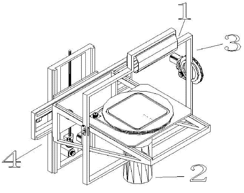
[0042] The technical solution of the present invention will be further described below in conjunction with the accompanying drawings.

[0043] Such as figure 1 , Figure 12 As shown, the micro-focus X-ray precision fluoroscopic imaging detection equipment of the present invention includes a micro-focus X-ray source, a radiographic receiver, a multi-angle rotating three-dimensional detection device for the X-ray emission source and receiver, a four-axis motion platform for the measured object, and a computer And the five functional parts of the layered control (image processing and motion control) system.

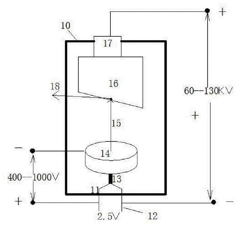
[0044] A microfocus X-ray source.

[0045] It consists of a micro-focus X-ray tube and a corresponding power supply.

[0046] Such as figure 2 In the X-ray tube structure and working principle diagram shown, the micro-focus X-ray tube is a cylindrical glass tube 10 with internal vacuum, which is composed of a filament pole, a focusing pole and an anode.

[0047] The fi...


PUM


Abstract

The invention relates to micro-focus X-ray precise perspective imaging detection equipment applied in the field of electronic and micro-electronic assembly, belonging to nondestructive full-automatic detection equipment and comprising a micro-electronic X-ray source, a ray image receiver, an X-ray emitting source, a multi-angle rotating three-dimensional detection device of a receiver, a four-axis mobile platform of a detected object, a computer and a layering control system, wherein the multi-angle rotating three-dimensional detection device and the four-axis mobile platform of the detected object are assembled into a mobile bracket body; the detected object is arranged on the four-axis mobile platform; the micro-electronic X-ray source and the ray image receiver are respectively arranged at the two ends of a bracket of the multi-angle rotating three-dimensional detection device; and the computer and the layering control system finish real-time mobile control and real-time image acquisition and processing. The invention is a new-generation nondestructive detection equipment which is especially applied in detection of electronic and micro-electronic products and production detection of various fine industries, thus being applied in the fields such as aviation, aerospace, military and industry.

Description

technical field [0001] The invention relates to a non-destructive automatic detection device, in particular to a micro-focus X-ray precision perspective imaging detection device used in the field of electronics and microelectronic assembly. Background technique [0002] X-ray imaging has been widely used in human body imaging and medicine, that is, the absorption of X-rays by different organs and tissues of the human body can be characterized by tissue density, and X-ray fluoroscopy and X-ray radiography have been developed, which can be used for human bones and internal organs. Diagnosis and localization of diseases or injuries of organs and blood vessels. [0003] At present, the main methods of non-destructive testing are: film photography method, image intensifier real-time imaging method, industrial CT imaging method, etc. Except for the industrial CT imaging method, other methods can only be used for two-dimensional imaging, and cannot obtain detailed information on t...

Claims


Application Information

Patent Timeline
Patent Type & Authority Applications(China)
IPC IPC(8): G01N23/04
Inventor 孙珂孙嘉德趙越堂
Owner SHANGHAI MODERN TECH
Why Eureka
Try Eureka