Patient-specific spinal fusion cage and methods of making same

a patient-specific and cage-making technology, applied in the field of patient-specific spinal fusion cages and methods of making same, can solve the problems of insufficient contact area, cage expulsion from disc space, cage to settle or subside into the vertebral body, etc., and achieve the effect of reducing subsidence and expulsion, and maximizing contact area

Active Publication Date: 2017-09-12
DEPUY SYNTHES PROD INC
View PDF29 Cites 30 Cited by
  • Summary
  • Abstract
  • Description
  • Claims
  • Application Information

AI Technical Summary

Benefits of technology

[0007]The present invention relates to the intra-operative determination of a desired cage footprint, height, lordosis, 3D geometry and endplate contact area, once spinal disc space intervention and decompression have been achieved and spinal alignment has been determined. The present invention provides certain patient-specific spinal fusion cages as well as the method of determination, fabrication and implantation of these patient-specific spinal fusion devices. This method and devices allow for the intra-operative determination, fabrication and implantation of custom, patient-specific implants to maximize contact area between the prepared endplates and the fusion cage with the objective of reducing subsidence and expulsion.

Problems solved by technology

Spinal fusion cage subsidence and expulsion are frequently issues of concern in spinal fusion surgeries.
Insufficient contact area and load transfer between the vertebral body and the cage can produce excessive load transfer in specific locations that can lead the cage to settle or subside into the vertebral body.
Insufficient contact area or pressure differentials between the cage and the vertebral bodies can also produce micro-motions and / or macro-motions that can increase subsidence and result in cage expulsion from the disc space.
It is believed that this insufficient contact area is in part due to the anatomical variability in the curvature of the endplates from level to level and patient to patient.
Additionally, low bone mineral density index or overaggressive decortications of the endplate can reduce the strength of the endplate and the ability to transfer load from vertebral body to vertebral body.
Although some cages have been domed to increase contact area, these are often unable to fit and conform to each disc space due to inherent human anatomical variability.
A significant limitation with these devices and patents is that they assume the correct disc space geometry can be clearly identified prior to surgical intervention for disc space released, FSU decompression and spinal alignment corrections.
Additionally, the state of the art does not include patient-specific intra-operatively fabricated cages nor patient-specific intra-operatively assembled cages.

Method used


Image

  • Patient-specific spinal fusion cage and methods of making same
  • Patient-specific spinal fusion cage and methods of making same
  • Patient-specific spinal fusion cage and methods of making same

Examples


Embodiment Construction

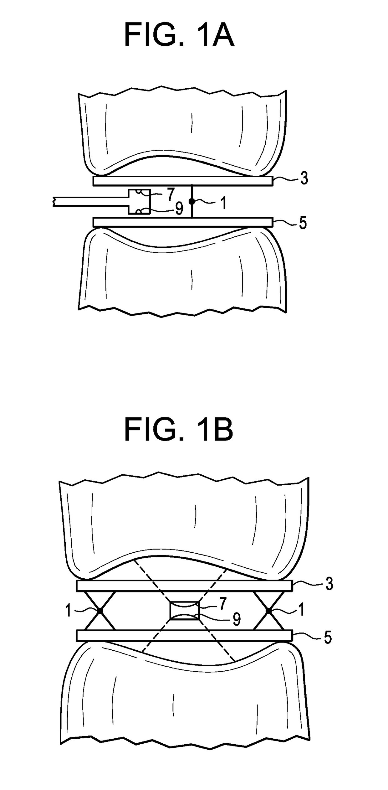
[0036]In general, the trial of the present invention comprises the aforesaid distal portion, a proximal end portion comprising a handle, and an elongated intermediate portion. Preferably, the elongated intermediate portion comprises a rod. Also preferably, the upper and lower surfaces are substantially planar.

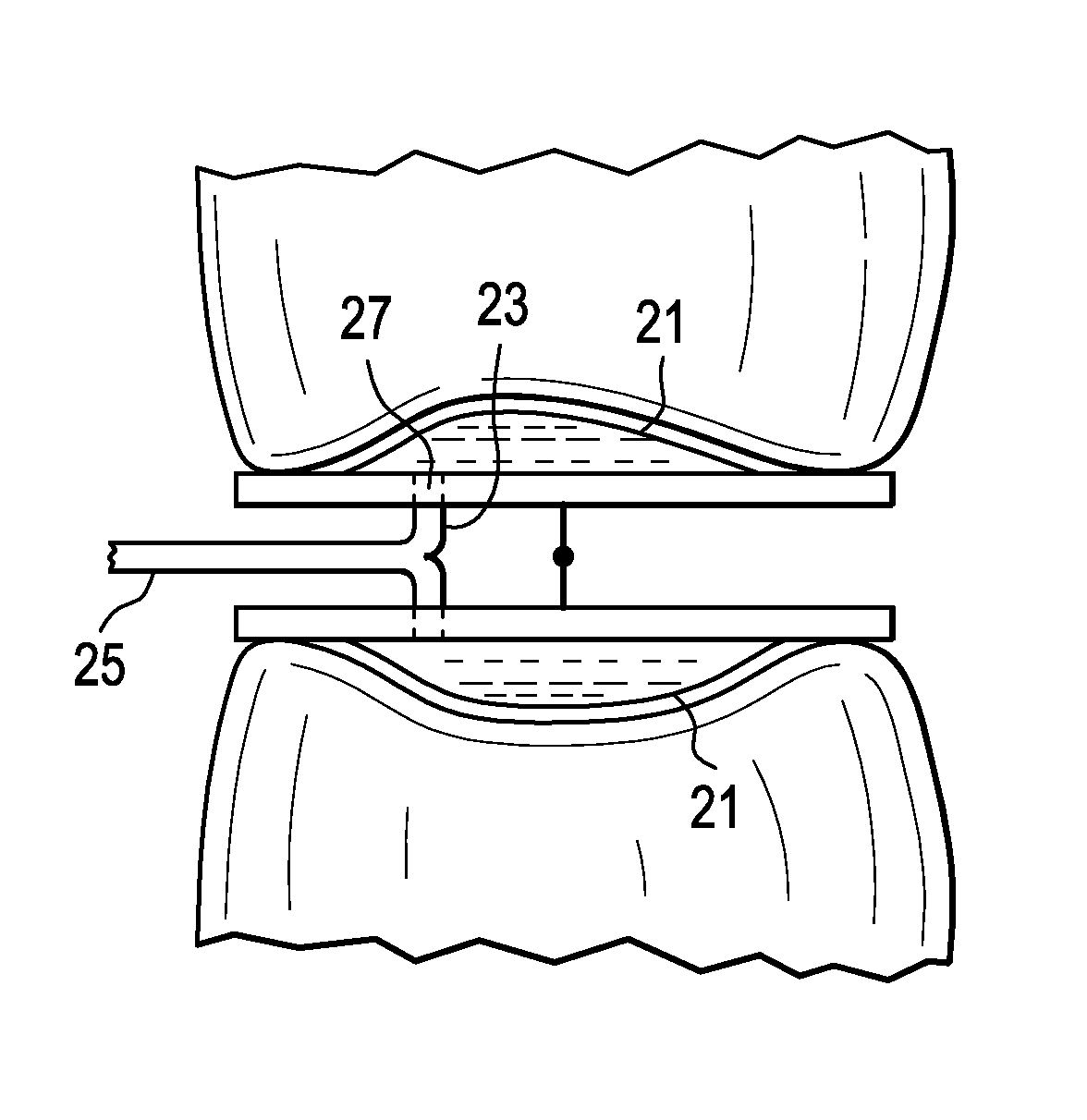
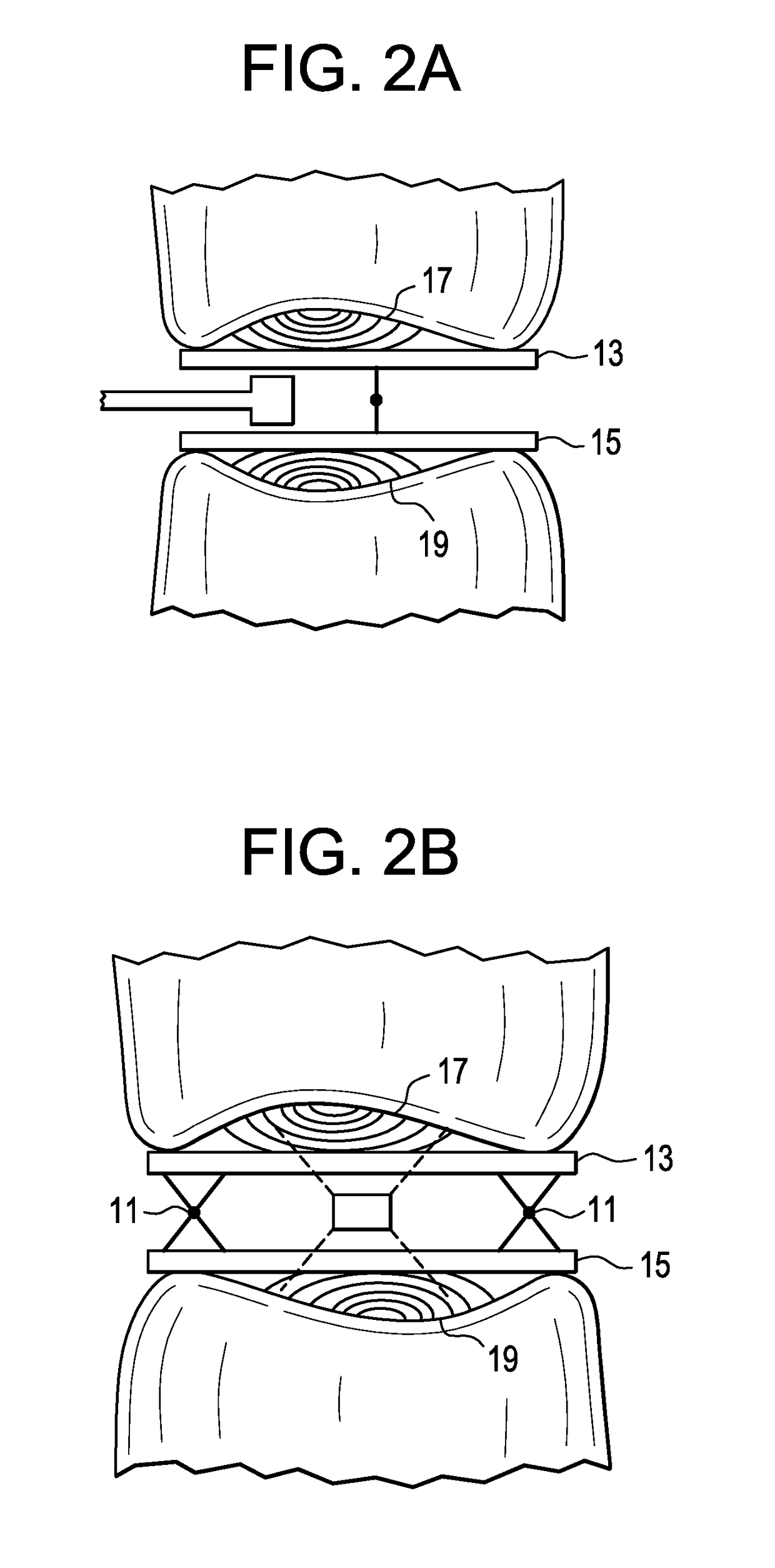
[0037]In one embodiment of the invention, the imaging feature comprises an endoscope having a light emitter, such as a fiber optic. In this embodiment, the light emitter emits light waves into the cavity between the trial and the vertebral endplate to create return signals. A monitoring system including a camera creates a 3D image of the cavity from the return signals. A screen may also provide a visual identification of the endplate contour.

[0038]In one embodiment, the fiber optic emits light waves from a tip of a fiber optic into the cavity between the vertebral endplate and the trial. Light waves are emitted at frequencies sufficient to image endplate contours. In this embod...


PUM

PropertyMeasurementUnit
heightaaaaaaaaaa
light absorption imagingaaaaaaaaaa
areaaaaaaaaaaa

Abstract

A method of determining disc space geometry with the use of an expandable trial having endplate-mapping capabilities. An expandable trial is inserted into the disc space and its height is adjusted to obtain the desired decompression and spinal alignment (which is typically confirmed with the use of CT or Fluoroscopic imaging). The endplate dome / geometry dome is then determined by one of the following three methods:a) direct imaging through the trial,b) balloon moldings filled with flowable in-situ fluid (for example, silicon, polyurethane, or PMMA) from superior / inferior endplates orc) light-based imaging through superior & inferior balloons.

Description

BACKGROUND OF THE INVENTION[0001]Spinal fusion cage subsidence and expulsion are frequently issues of concern in spinal fusion surgeries. Restenosis due to subsidence has been often documented. See, for example, Marchi et al., J Neurosurg Spine 19, 110-118, 2013. Four subsidence grades have been developed and shown to correlate with the likelihood of restenosis and associated revision rates. The significant potential of endplate-conforming implants in reducing the likelihood of subsidence has also been considered. See, for example, de Beer et. al., Spine Journal 12, 1060-1066, 2012.[0002]Insufficient contact area and load transfer between the vertebral body and the cage can produce excessive load transfer in specific locations that can lead the cage to settle or subside into the vertebral body. Insufficient contact area or pressure differentials between the cage and the vertebral bodies can also produce micro-motions and / or macro-motions that can increase subsidence and result in ca...

Claims


Application Information

Patent Timeline
Patent Type & Authority Patents(United States)
IPC IPC(8): A61B17/70A61F2/44A61B5/00A61B8/12A61F2/30A61F2/46
CPCA61F2/442A61B5/0084A61B5/45A61B8/12A61F2/30942A61F2/4455A61F2/4684A61F2002/30387A61F2002/30556A61F2002/30579A61F2002/30581A61F2002/30604A61F2002/30971A61F2002/30985A61F2002/469A61F2002/4663A61F2002/4689A61F2002/4696
Inventor O'NEIL, MICHAEL JLOMELI, ROMAN
Owner DEPUY SYNTHES PROD INC
Why Eureka
Try Eureka