
Downhole Local Mud Weight Measurement Near Bit

a local mud weight and drilling technology, applied in the field of oilfield downhole tools, can solve the problems of well blowout at the surface, loss of drilling fluid into a formation, hazard to equipment and personnel, etc., and achieve the effect of reducing the relative offs

Active Publication Date: 2009-08-20
BAKER HUGHES INC
View PDF10 Cites 21 Cited by
  • Summary
  • Abstract
  • Description
  • Claims
  • Application Information

AI Technical Summary

Benefits of technology

[0007]In aspects, the present disclosure provides a method for detecting a change in a fluid in a wellbore. In one embodiment, the method includes estimating a first and a second pressure difference in the fluid in the wellbore; and estimating a change in a density of the fluid using the first and the second pressure differences. In some embodiments, the change in density is in part estimated by the equation, Δρ=(ΔPbefore<sub2>—< / sub2>influx−ΔPafter<sub2>—< / sub2>influx) / (g×ΔTVD), wherein Δρ is a fluid pressure difference between a first and second point along the wellbore, ρ is a mean value of density of the fluid between the first and the second point, g is gravity and ΔTVD is a vertical distance between the first and the second point. Also, the method may include estimating an inclination along the wellbore, and estimating a change in the density using the estimated inclination. An exemplary apparatus deployed in connection with the method may include at least two axially spaced apart pressure sensors to estimate the first and the second pressure differences. In one arrangement, the method may further include the steps of switching the positions of the two pressure sensors; measuring pressure with the two pressure sensors in their switched positions; estimating a correction term using the pressure measurement of the two pressure sensors in their switched and unswitched positions; and applying the estimated correction term to the measurements of the pressure sensors to reduce a relative offset between the two pressure sensors.

Problems solved by technology

During construction or servicing of a hydrocarbon producing well, an operator can encounter a number of undesirable conditions that can pose a hazard to equipment and personnel.
One undesirable condition is a “kick.” During drilling, a high pressure formation fluid can invade the well bore and displace drilling fluid from the well.
The resulting pressure “kick” can lead to a well blow-out at the surface.
Another undesirable condition is a loss of drilling fluid into a formation.
Yet another undesirable condition is an underground blowout, which is generally understood as an undesirable subsurface cross flow between two reservoirs intersected by a wellbore.
The shut-in well can cause an annulus pressure increase that fractures one or more zones in an open hole region.

Method used


Image

  • Downhole Local Mud Weight Measurement Near Bit
  • Downhole Local Mud Weight Measurement Near Bit
  • Downhole Local Mud Weight Measurement Near Bit

Examples


Embodiment Construction

[0017]The present disclosure relates to devices and methods for obtaining estimations of changes in drilling fluid density at or near a drill bit or elsewhere along a wellbore. The present disclosure is susceptible to embodiments of different forms. There are shown in the drawings, and herein will be described in detail, specific embodiments of the present disclosure with the understanding that the present disclosure is to be considered an exemplification of the principles of the disclosure, and is not intended to limit the disclosure to that illustrated and described herein. Further, while embodiments may be described as having one or more features or a combination of two or more features, such a feature or a combination of features should not be construed as essential unless expressly stated as essential.

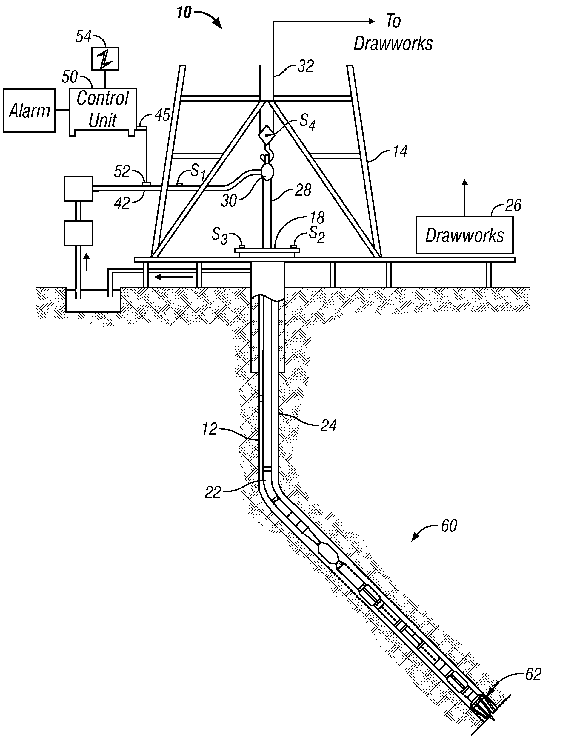
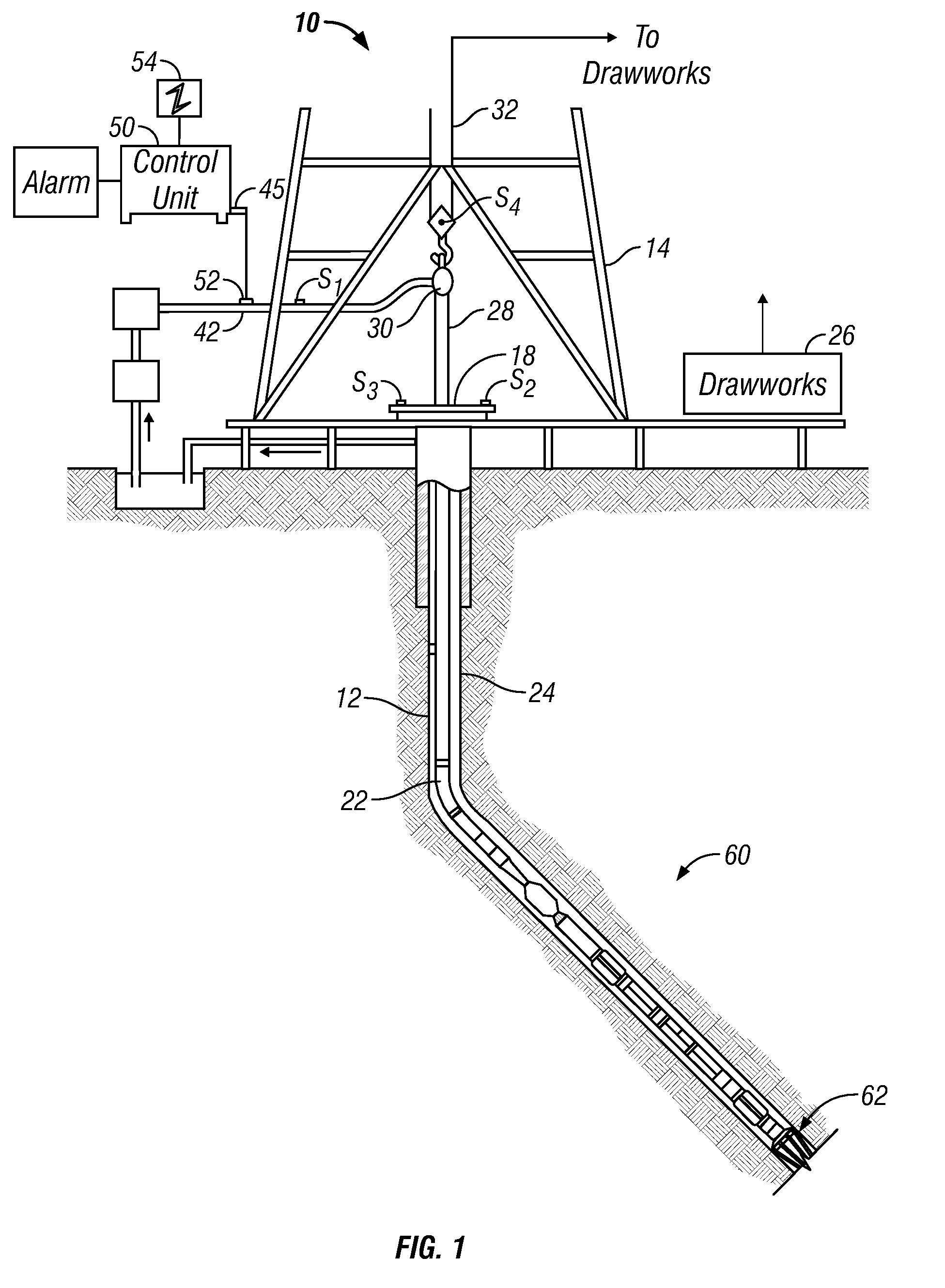
[0018]Referring now to FIG. 1, there is shown an embodiment of a drilling system 10 utilizing a bottomhole assembly (BHA) 60 configured for drilling wellbores. As will be apprecia...


PUM


Abstract

A method for detecting a change in a wellbore fluid includes estimating at least two pressure differences in the wellbore fluid and estimating a change in a density of the fluid using the at least two pressure differences. The density change may be estimated by the equation, Δρ=(ΔPbefore<sub2>—< / sub2>influx−ΔPafter<sub2>—< / sub2>influx) / (g×ΔTVD), wherein ΔP is a fluid pressure difference between two points along the wellbore, ρ is a mean value of density of the fluid between the two points, g is gravity and ΔTVD is a vertical distance between the two points. The method may include estimating a density change using an estimated inclination of the wellbore. An apparatus for estimating density changes includes at least two axially spaced apart pressure sensors. The sensor positions may be switched to estimate a correction term to reduce a relative offset between the two pressure sensors.

Description

CROSS-REFERENCE TO RELATED APPLICATIONS[0001]This application takes priority from the U.S. Provisional Application Ser. No. 61 / 029,762, filed on Feb. 19, 2008.BACKGROUND OF THE DISCLOSURE[0002]1. Field of the Disclosure[0003]This disclosure relates generally to oilfield downhole tools and more particularly to methods and devices for enhanced directional drilling of wellbores.[0004]2. Description of the Related Art[0005]During construction or servicing of a hydrocarbon producing well, an operator can encounter a number of undesirable conditions that can pose a hazard to equipment and personnel. One undesirable condition is a “kick.” During drilling, a high pressure formation fluid can invade the well bore and displace drilling fluid from the well. The resulting pressure “kick” can lead to a well blow-out at the surface. Conventionally, during drilling, the mud weight of a drilling fluid circulated in the well is selected to provide a hydrostatic pressure that minimizes the risk and i...

Claims


Application Information

Patent Timeline
IPC IPC(8): E21B47/00E21B47/06G06F19/00
CPCE21B47/06E21B21/08G01N9/26E21B21/06
Inventor DIFOGGIO, ROCCOZHAO, JINSONG
Owner BAKER HUGHES INC
Learn More