Central floor part of a vehicle body

a technology of floor assembly and vehicle body, which is applied in the direction of monocoque construction, superstructure subunits, understructures, etc., can solve the problem of slightly more difficult installation in the vehicle body, and achieve the effect of simple production

Inactive Publication Date: 2009-08-20
DR ING H C F PORSCHE AG
View PDF29 Cites 11 Cited by
  • Summary
  • Abstract
  • Description
  • Claims
  • Application Information

AI Technical Summary

Benefits of technology

[0005]It is accordingly an object of the invention to provide a central floor part of a vehicle body that overcomes the above-mentioned disadvantages of the prior art devices of this general type, which is simple to produce.

Problems solved by technology

This permits the use of relatively small dies in the production process, but is for this reason slightly more difficult to install in the vehicle body.

Method used


Image

  • Central floor part of a vehicle body
  • Central floor part of a vehicle body
  • Central floor part of a vehicle body

Examples


Embodiment Construction

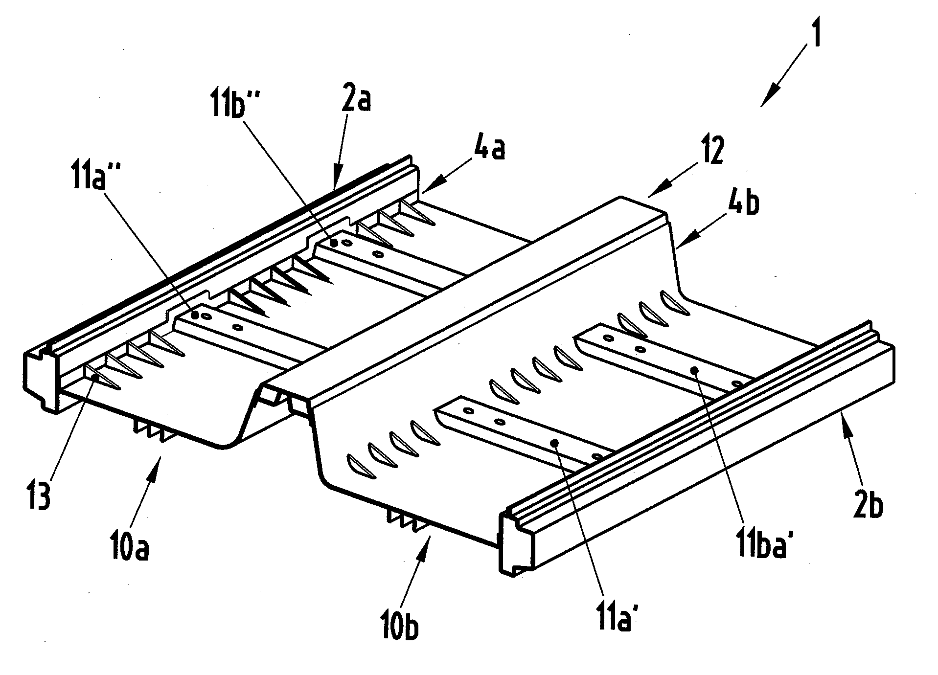
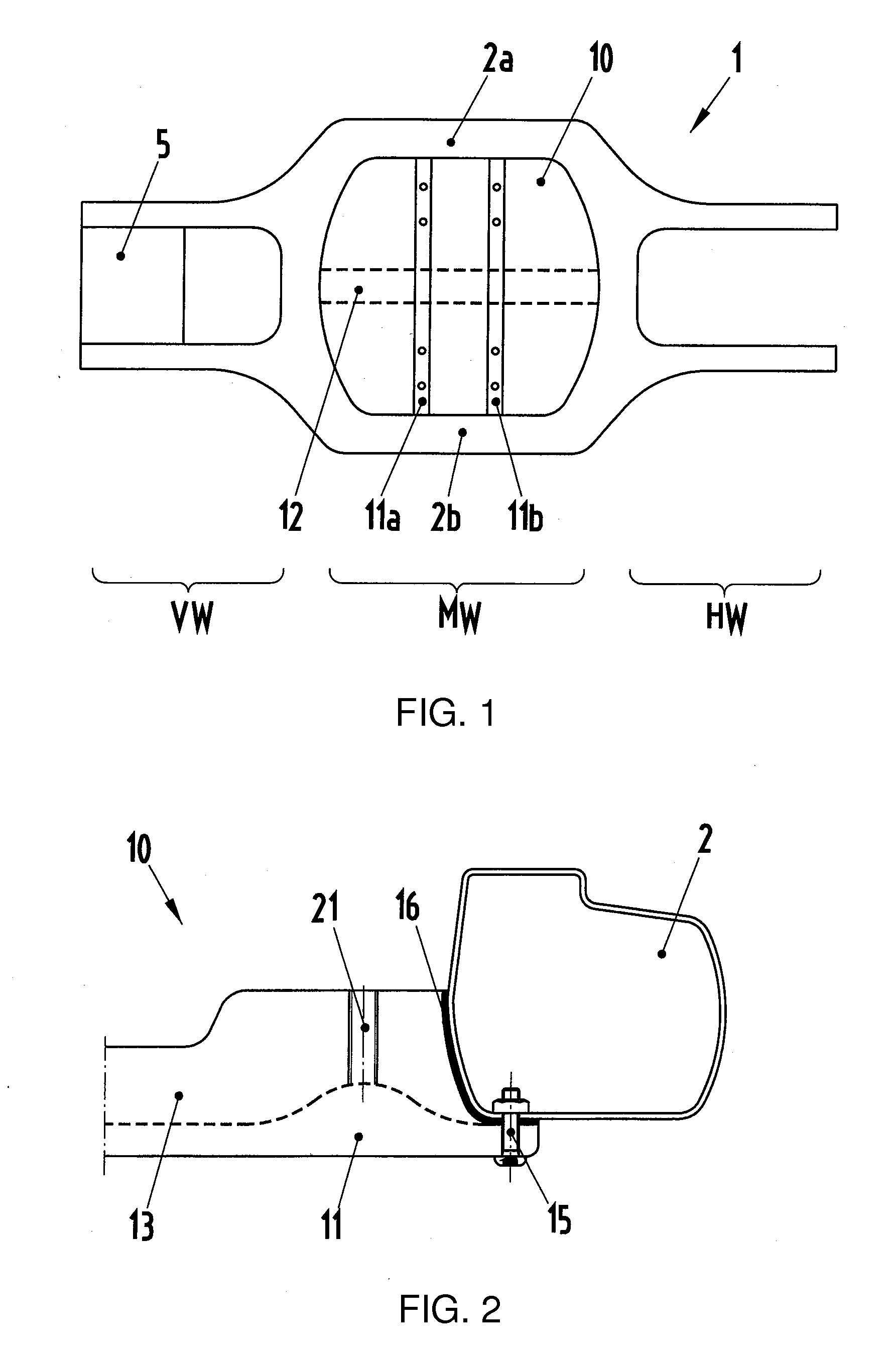
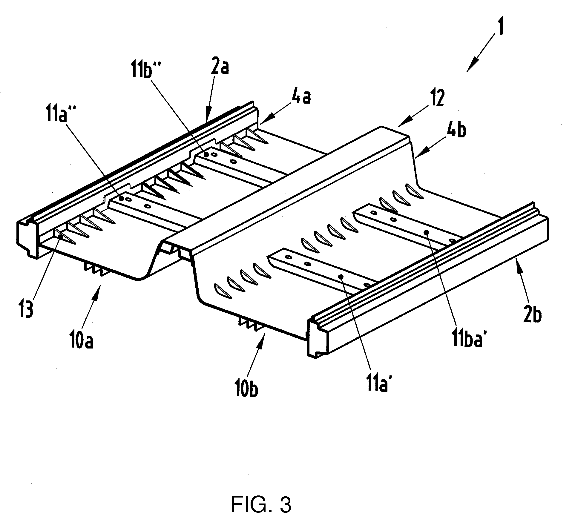
[0021]Referring now to the figures of the drawing in detail and first, particularly, to FIG. 1 thereof, there is shown a floor assembly 1 of a vehicle body, having a central floor part 10 according to the invention. Here, the central floor part 10 is disposed between two sill profiles 2a and 2b. Also schematically shown is the position of the central floor part 10 in the vehicle central section MW of the vehicle body, which vehicle central section is adjoined by a vehicle front end VW and a vehicle rear end HW. Since a rear-wheel-drive vehicle is illustrated in the present case, the luggage compartment floor 5 is provided in the region of the vehicle front end VW. The luggage compartment floor 5 may likewise be produced similarly to the central floor part 10 according to the invention. Additionally indicated are an optional vehicle tunnel 12 and front and rear transverse seat supports 11a and 11b for holding fastening points of the vehicle seats. FIG. 2 schematically shows the conne...


PUM


Abstract

A central floor part of a floor assembly of a vehicle body is formed as a unipartite cast part which is delimited at the outer side of the body by in each case one sill profile. Alternatively the unipartite cast part can be two cast parts connected to each other by a vehicle tunnel disposed between the inner sides of the two cast parts.

Description

CROSS-REFERENCE TO RELATED APPLICATION[0001]This application claims the priority, under 35 U.S.C. §119, of German application DE 10 2008 009 804.3, filed Feb. 19, 2008; the prior application is herewith incorporated by reference in its entirety.BACKGROUND OF THE INVENTION[0002]1. Field of the Invention[0003]The invention relates to a central floor part of a floor assembly of a vehicle body.[0004]Published, non-prosecuted German patent application DE 10 2004 062 933 A1 discloses a floor assembly of a motor vehicle body, having a central floor part which is formed as a closed surface and which is formed from a multiplicity of floor profiles which are arranged adjacent to one another and which point substantially in the vehicle longitudinal direction. The central floor part is adjoined by a vehicle rear end which is formed as an integral cast component, composed of two longitudinal members and two transverse members, as an open support structure.SUMMARY OF THE INVENTION[0005]It is acco...

Claims


Application Information

Patent Timeline
Patent Type & Authority Applications(United States)
IPC IPC(8): B62D25/20
CPCB62D21/07B62D21/10B62D25/2036B62D25/20B62D25/025B60N2/015
Inventor BIERSACK, HARALD
Owner DR ING H C F PORSCHE AG
Why Eureka
Try Eureka