Magnetic Resonance Imaging Apparatus and Method

Active Publication Date: 2009-08-20
FUJIFILM HEALTHCARE CORP
View PDF12 Cites 1 Cited by
  • Summary
  • Abstract
  • Description
  • Claims
  • Application Information

AI Technical Summary

Benefits of technology

[0007]The objective of the present invention is to provide an MRI apparatus and method capable of reducing artifacts generated in the unfolded image in which parallel imaging is used, whereby generating high-quality images.
[0017]means for updating the sensitivity distribution information in the respective background regions by mutually using the sensitivity distribution information of each of the plurality of high-frequency receiver coils thereby to suppress the noise component contained in the unfolded image.
[0023](5) a step for updating the sensitivity distribution information in the respective background regions mutually using the sensitivity distribution information of the plurality of high-frequency receiver coils, thereby to suppress noise components contained in the unfolded images.
[0024]In accordance with the above-mentioned present invention, an MRI apparatus and method are provided capable of reducing artifacts generated on the unfolded images in parallel imaging and generating high-quality images.

Problems solved by technology

However, in the parallel imaging method described in Patent Document 1, the image obtained by unfolding process had problems being constrained and having new artifacts generated due to drastic decline of sensitivity information in the boundary between the object region and the background region.

Method used


Image

  • Magnetic Resonance Imaging Apparatus and Method
  • Magnetic Resonance Imaging Apparatus and Method
  • Magnetic Resonance Imaging Apparatus and Method

Examples


embodiment 1

[0055]First, an example of the pulse sequence to be applied in embodiment 1 will be described referring to FIG. 4. The pulse sequence shown in FIG. 4 is a spin echo method, irradiation of RF pulse 401 and gradient magnetic field pulse 402 for slice selection are simultaneously applied first, and only the target fault plane is excited. Next, gradient magnetic field pulse 403 for phase encoding is applied in order to encode the positional information. Then the phase of proton dispersed over time is inverted 180 degrees, the phases are aligned again, and RF pulse 404 and gradient magnetic field pulse 405 for slice selection are irradiated to cause the echo signals generated.

[0056]Finally, gradient magnetic field pulse 406 for signal readout is applied, and the echo signals are collected as indicated by 407.

[0057]FIG. 5 is a schematic view showing the case of calculating sensitivity information (sensitivity distribution) of the respective small RF receiver coils in embodiment 1 of the p...

embodiment 2

[0101]Next, embodiment 2 will be described. Embodiment 2 is another example of weighting function used in step 1005 of embodiment 1. The function to be used in embodiment 2 is referred to as the piecewise linear function, and represented in the following formula 26 and in FIG. 13. In this regard, however, when formula 26 is expressed in a general formula, it will be expressed as formula 27.

β(x,y)=1 (r′(x,y)<1)

β(x,y)=−1 / 2×r′(x,y)+2 (1≦r′(x,y)≦=3)

β(x,y)=0 (3<r′(x,y))  [Formula 26]

η=1 (λa)

η=−c×λ+a×c+1 (a≦λ≦a+1 / c)

η=0 (a+1 / c<λ)  [Formula 27]

[0102]In formula 27, “a” is a starting point of the linear function, and “c” is a slope of the linear function (sign inversion). When the piecewise linear function in this embodiment is used, the weighting coefficient can also be obtained by making the change of the matrix elements in sensitivity distribution small in the region having high signal intensity in the whole sensitivity image, and by making the change of matrix in sensitivity distributi...

embodiment 3

[0103]Next, embodiment 3 will be described. Embodiment 3 is another example of the weighting function to be used in step 1105 of embodiment 1. The function to be used in embodiment is referred to as the piecewise cosine function, and is represented in the following formula 28 and in FIG. 14. In this regard, however, formula 28 is expressed as formula 29 when expressed in general formula.

β(x,y)=1 (r′(x,y)<1)

β(x,y)=0.5+0.5×cos(π / 2*(r′(x,y)−1)) (1≦r′(x,y)≦3)

β(x,y)=0 (3<r′(x,y))  [Formula 28]

η=1 (λa)

η=0.5+0.5×cos(η / *(λ−a)) (a≦λ≦a+d)

η=0 (a+d<λ)  [Formula 29]

[0104]In formula 29, “a” represents a starting point of the cosine function, and “d” represents the range of the cosine function. When the piecewise cosine function in the present embodiment is used, the weighting function can also be obtained by making the change of the matrix elements in sensitivity distribution small in the region having high signal intensity in the whole sensitivity image, and by making the change of matrix ele...


PUM


Abstract

A magnetic resonance imaging apparatus comprises a plurality of high-frequency reception coils, sensitivity distribution information obtaining means for calculating sensitivity distribution information of each of the high-frequency reception coil, sensitivity distribution storage means for storing the sensitivity distribution information, measuring means for acquiring magnetic resonance signals by thinning out encode steps of a k-space, image reconstructing means for reconstructing images using the magnetic resonance signals, and means for performing unfolding calculation using the sensitivity distribution information and the image, thereby to acquire the unfolded image.The magnetic resonance imaging apparatus further comprises means for estimating the sensitivity distribution information of a background region by using the sensitivity distribution information of an object region, and means for updating the background region by mutually using the sensitivity distribution information of the respective high-frequency receptions coils thereby to suppress noise component contained in the unfolded image.

Description

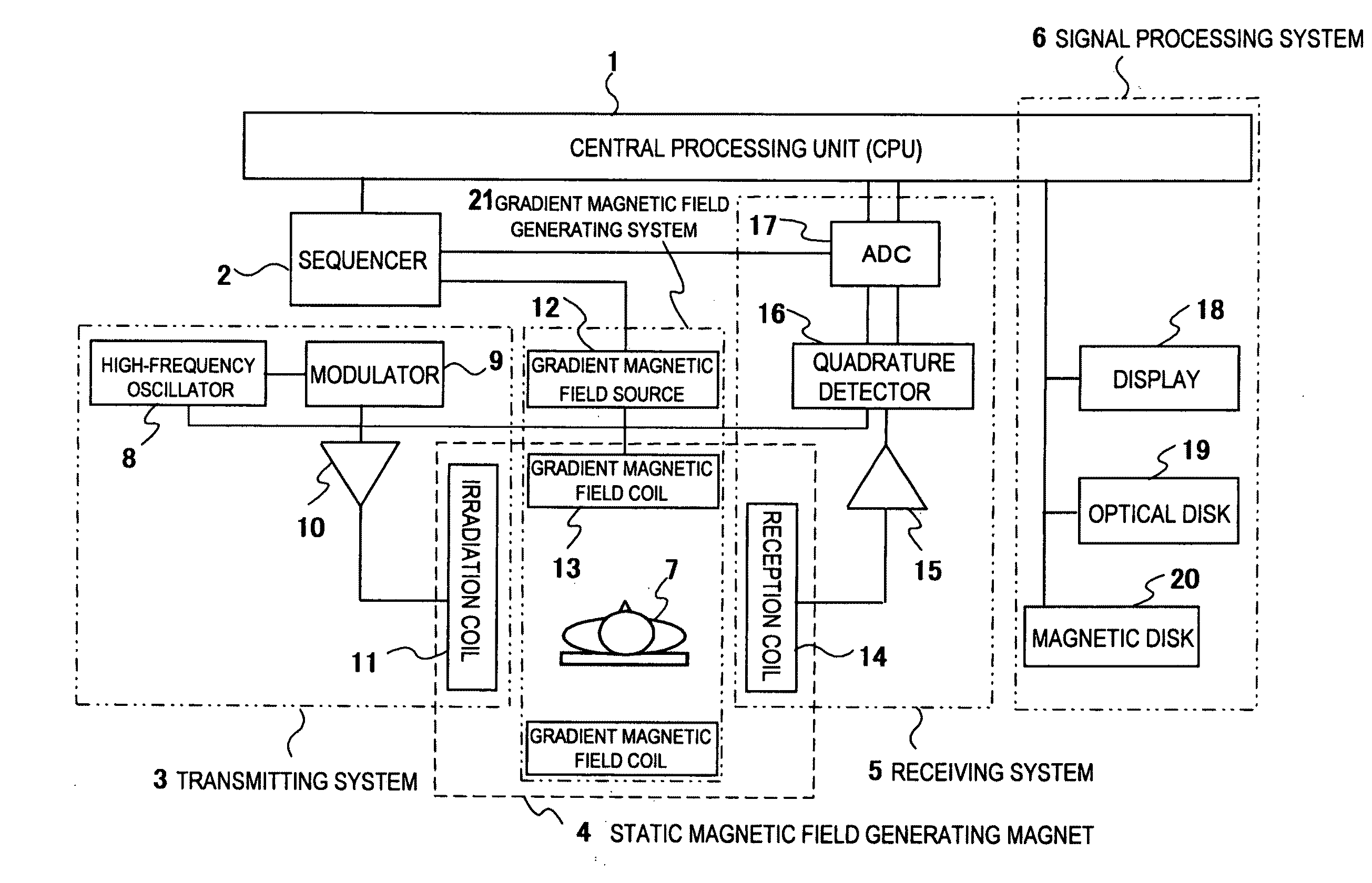
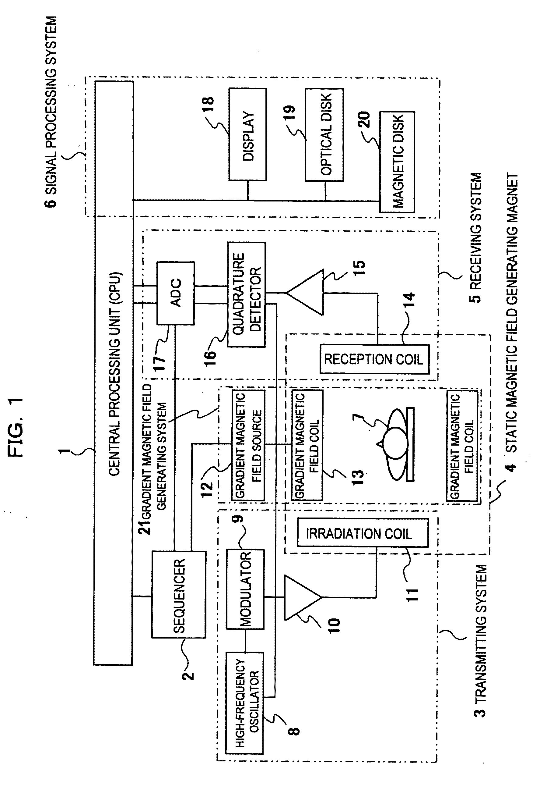
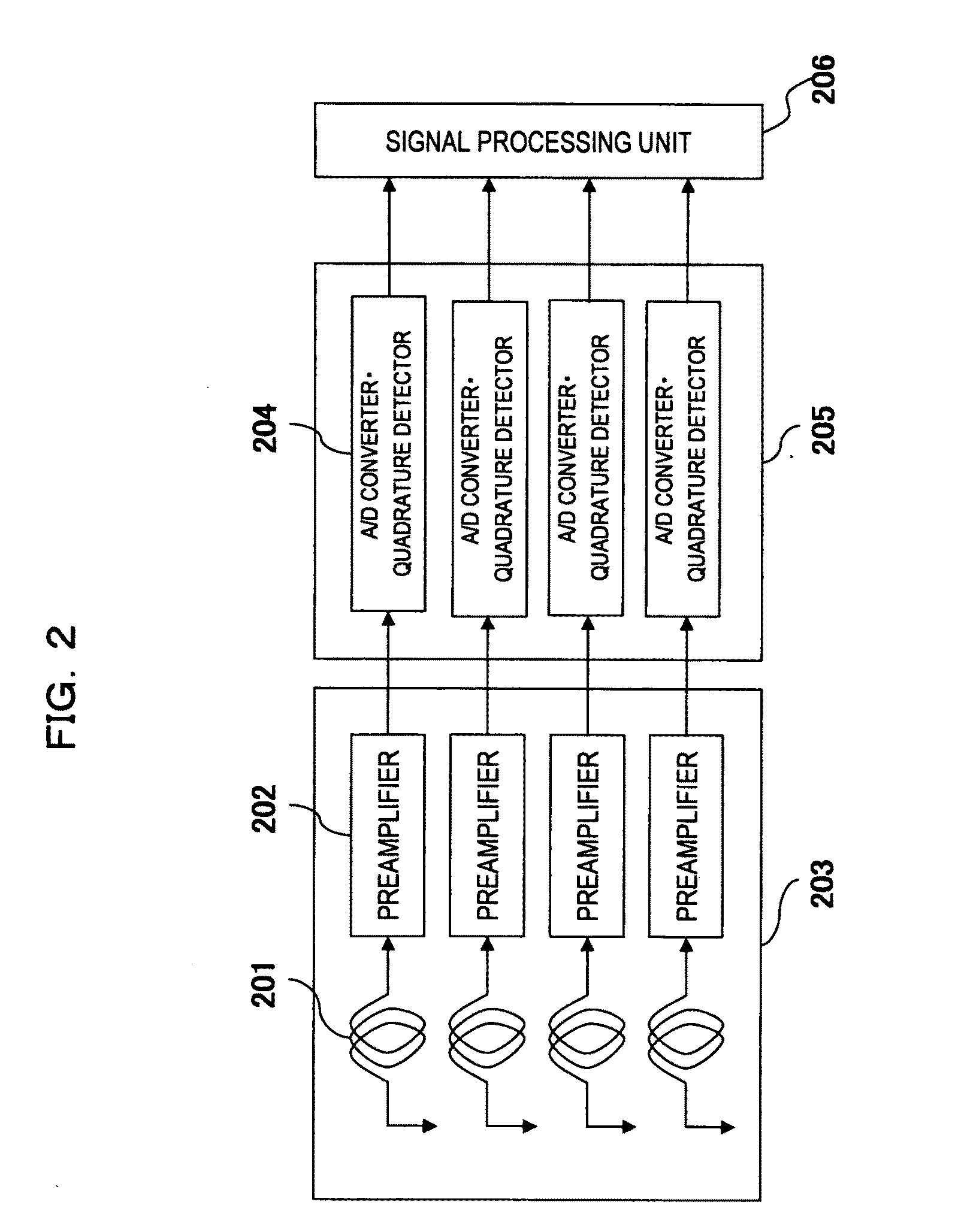
TECHNICAL FIELD[0001]The present invention relates to a magnetic resonance imaging apparatus (hereinafter referred to as an MRI apparatus) and method, particularly to a technique for improving image quality using a parallel imaging method.BACKGROUND ART[0002]Recently in MRI apparatuses, the coils referred to as multiple RF coils or phased array coils are heavily used as a reception coil for detecting NMR signals generated from an object to be examined. This type of coil is configured arranging a plurality of high sensitivity small RF receiver coils. Also, an imaging method by thinning out phase encodes through the usage of multiple RF coils is disclosed in Patent Document 1.[0003]This method is referred to as a parallel imaging method, and is for eliminating aliasing generated upon thinning out phase encodes using a character by which sensitivity distribution of the plurality of small RF receiver coils that are forming the multiple RF coil are spatially and mutually different.[0004]...

Claims


Application Information

Patent Timeline
IPC IPC(8): G01R33/48G06K9/00
CPCG01R33/5611
Inventor NAKAI, NORIMASA
Owner FUJIFILM HEALTHCARE CORP
Why Eureka
Try Eureka