Extinction ratio control using a frequency spread tone to modulate optical signal power levels

Active Publication Date: 2009-08-20
II VI DELAWARE INC
View PDF9 Cites 11 Cited by
  • Summary
  • Abstract
  • Description
  • Claims
  • Application Information

AI Technical Summary

Benefits of technology

[0019]Accordingly, an optical power level of the optical signal is modulated with a frequency spread tone thereby improving extinction ratio control. Additional features and advantages of the invention will be set forth in the description that follows, and in part will be obvious from the description, or may be learned by the practice of the invention. The feature

Problems solved by technology

The laser is not turned off because it takes significant time to saturate a laser to the point where it begins to lase if starting from a laser that is off.
In fact, if the current through the laser were to drop below a certain threshold current, it can take much longer to transition to the high optical intensity.
In high data rate applications, this could cause significant jitter and possible degradation of the signal.
However, maintaining of a proper extinction ratio is more complex than simply statically determining an appropriate high optical level and an appropriate low optical level, and keeping with that level.
In addition,

Method used


Image

  • Extinction ratio control using a frequency spread tone to modulate optical signal power levels
  • Extinction ratio control using a frequency spread tone to modulate optical signal power levels
  • Extinction ratio control using a frequency spread tone to modulate optical signal power levels

Examples


Example

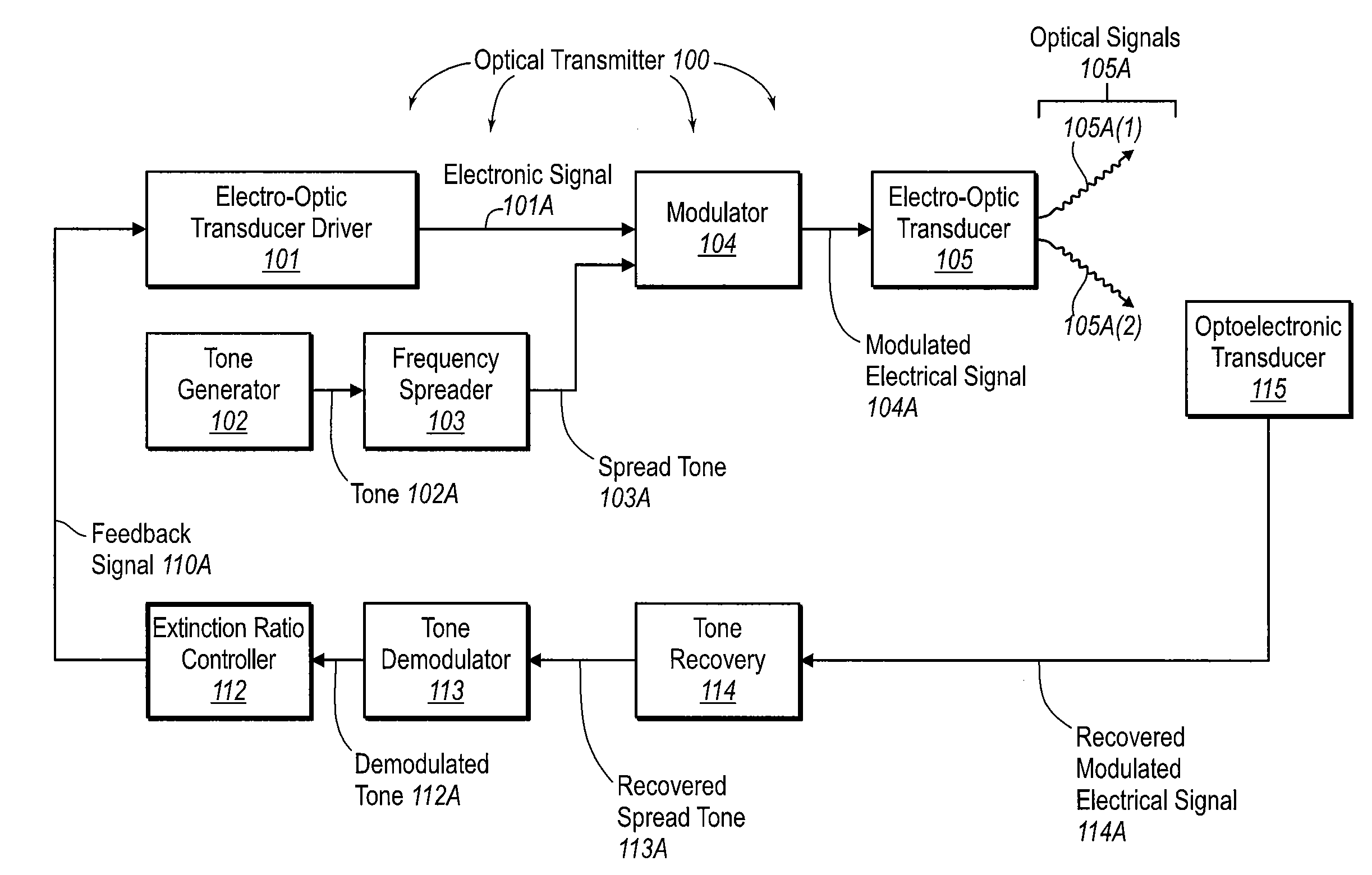
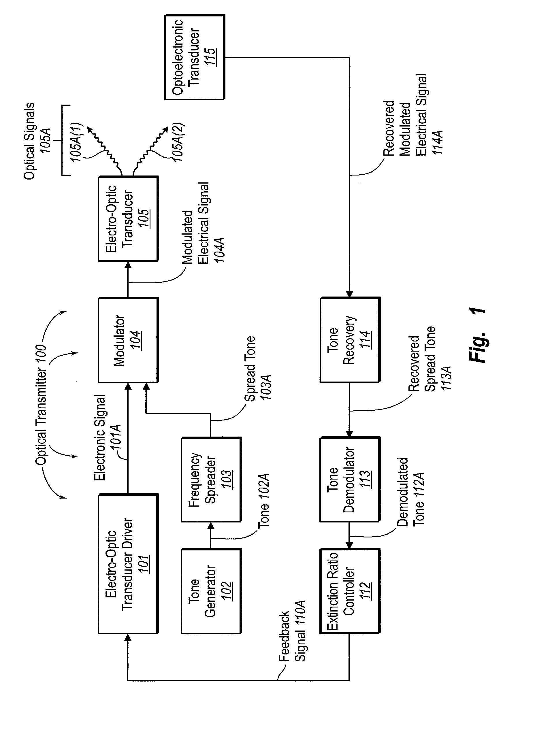
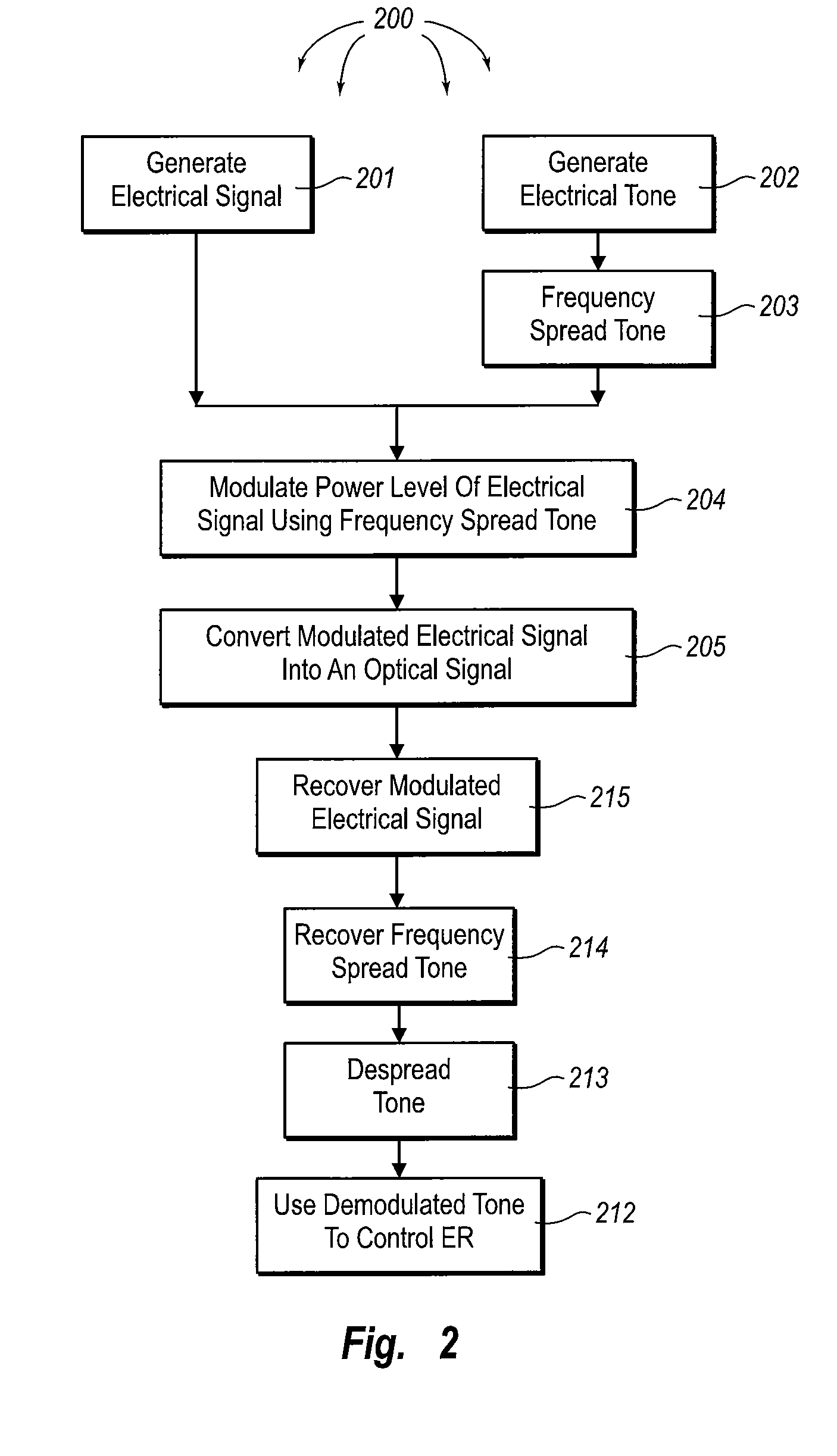
[0026]The principles of the present invention relate to an optical transmitter that controls the extinction ratio by modulating a power level of an optical signal using a frequency spread tone. By using the frequency spread tone, instead of a single tone, the tone may even be within the same frequency spectrum as the data thereby allowing for more flexibility on the frequency range of the spread tone. Furthermore, the spread tone contributes less interference to other portions of the optical transmitter that are perhaps susceptible to interference in the frequency of the tone before frequency spreading.

[0027]FIG. 1 illustrates an optical transmitter 100 in which the principles of the present invention may be employed. While the optical transmitter 100 will be described in some detail, the optical transmitter 100 is described by way of illustration only, and not by way of restricting the scope of the invention. The principles of the present invention are suitable for 1G, 2G, 4G, 10G ...


PUM


Abstract

An optical transmitter that controls the extinction ratio by modulating a power level of an optical signal using a frequency spread tone. An electro-optic transducer driver generates an electrical signal that is to be converted into an optical signal. Meanwhile, a tone generator generates an electrical tone having a relatively narrow frequency spectrum. A frequency spreading circuit frequency spreads the electrical tone. A modulator modulates a power level of the electrical signal using the frequency spread electrical tone. An electro-optic transducer then converts the modulated electrical signal into a corresponding optical signal. An optoelectronic transducer recovers the modulated electrical signal by monitoring the optical signal. The tone is then recovered from the signal, and demodulated. The demodulated tone is then used to control the extinction ratio.

Description

CROSS-REFERENCE TO RELATED APPLICATIONS[0001]This application claims the benefit of U.S. Provisional Application No. 60 / 717,344, filed Sep. 15, 2005, which is incorporated herein by reference in its entirety.BACKGROUND[0002]1. The Field of the Invention[0003]The present invention relates generally to optical transmitters. More specifically, the present invention relates to mechanisms for controlling the extinction ratio of an optical signal by modulating the optical signal levels using a frequency spread tone.[0004]2. Background and Relevant Art[0005]Computing and networking technology have transformed our world. As the amount of information communicated over networks has increased, high speed transmission has become ever more critical. Many high speed data transmission networks rely on optical transceivers and similar devices for facilitating transmission and reception of digital data embodied in the form of optical signals over optical fibers. Optical networks are thus found in a ...

Claims


Application Information

Patent Timeline
IPC IPC(8): H04J14/00H04B10/04
CPCH04J14/0298H04B10/50
Inventor HAUENSCHILD, JUERGENNGUYEN, THE-LINH
Owner II VI DELAWARE INC
Why Eureka
Try Eureka