
Sensor Net Management Method

a technology of sensor nets and management methods, applied in adaptive control, process and machine control, instruments, etc., can solve the problems of reducing the number of operating sensors, reducing the power of operation, and lowering the information precision

Active Publication Date: 2009-08-20
HITACHI LTD
View PDF5 Cites 35 Cited by
  • Summary
  • Abstract
  • Description
  • Claims
  • Application Information

AI Technical Summary

Benefits of technology

[0008]Since a sensor node is not able to operate when the battery has run out, it is necessary to monitor the run-out state of the battery and replace the battery or the sensor node itself. In order to extend the applicable scope of sensor nodes in the future, reliable sensor network is required. The reliable sensor network should cover a disadvantage of service interruption caused at the time of battery exhaustion or of failure in order to enhance its reliability.
[0009]In applications such as disaster monitoring and environmental monitoring performed by multiple sensor nodes located in many places in nature, sensor network is required to perform high-precision monitoring with full operation of the sensors when disaster risk is high or when sensing data shows large changes. However, at a low risk of disaster, the sensor network is required to reduce power in operation to extend the lifetime by lowering information precision, reducing the number of operating sensors, and reducing the sensing frequency. When a large change is not found in an observation object regarding sensing areas, a small number of observation points per unit area is enough. However, when a large change is found in an observation object regarding areas, it is required that observation be performed at more observation points. In other words, observation granularity (space and time) of sensor network should be modified flexibly in a desired manner by a user or the sensing state.
[0011]Therefore, an object of this invention is to realize a reliable sensor network which prevents service interruption. Another object is to provide a flexible management method in which observation granularity (space and time) can be modified in a desired manner by a user. Still another object is to provide a management method in which the lifetime of a sensor network is extended as long as possible by electric-power management of limited power-sensor nodes.
[0012]Specifically, an object of this invention is to provide a sensor node management method in which, even when some sensor nodes among multiple sensor nodes in intermittent operation fail, a user does not suffers service interruption. Another object is to provide a sensor node management method in which spatial and temporal observation granularities can be modified and the power saving in a sensor network can be realized, by manually or automatically changing the activation interval of each of multiple sensor nodes located in a sensing area based on user settings or interpretation of sensing data content.
[0016]As described above, since the nodes are grouped and managed, it is possible to provide a sensor node management method in which, even when some sensor nodes among multiple sensor nodes in intermittent operation have failed, a user does not suffers service interruption.
[0017]Further, the activation interval of each of multiple sensor nodes located in a sensing area is manually or automatically modified by changing observation intervals and the size of each group when the nodes are grouped, so it is possible to provide a sensor node management method in which spatial and temporal observation granularities can be modified.

Problems solved by technology

Since a sensor node is not able to operate when the battery has run out, it is necessary to monitor the run-out state of the battery and replace the battery or the sensor node itself.
However, at a low risk of disaster, the sensor network is required to reduce power in operation to extend the lifetime by lowering information precision, reducing the number of operating sensors, and reducing the sensing frequency.
Thus, the function of the conventional load balancer is not sufficient for sensor nodes that are expected to perform an intermittent operation.

Method used


Image

  • Sensor Net Management Method
  • Sensor Net Management Method
  • Sensor Net Management Method

Examples


Embodiment Construction

[0043]A description is given of a sensor network management system according to an embodiment of this invention.

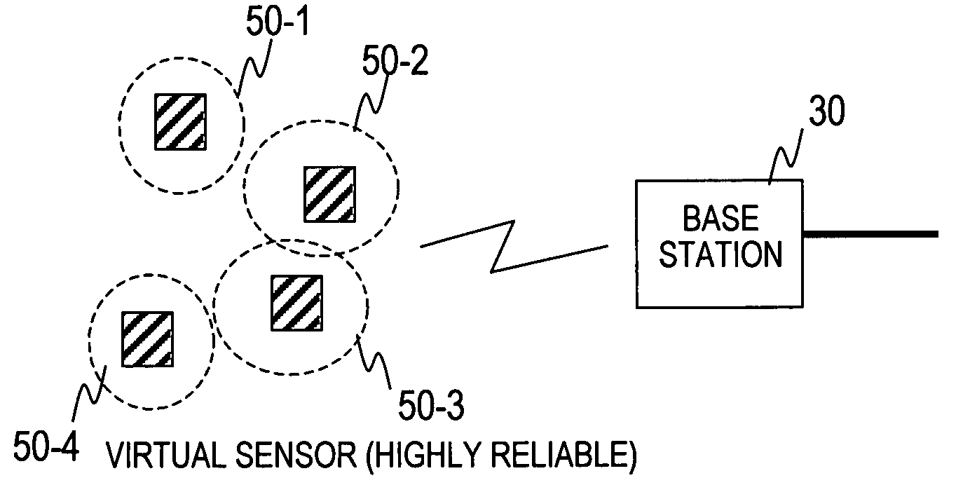
[0044]FIG. 5 shows an entire configuration of a sensor network system to which the sensor network management system of this invention is applied. Sensing information collected through a sensor network which includes multiple compact radio sensor nodes 10 are accumulated in base stations 30. The accumulated information is inputted to a server 20 via an existing network 110, for example, via a public network such as the Internet, or a private network. The server performs activation of an action corresponding to a change in sensing data, sensing data processing, sensing data accumulation processing, and the like. The function of the server 20 can be partially performed in the base stations 30 as well. An administrator can make settings for the server 20, the base stations 30, and the sensor nodes 10 and monitor them, via the network by using an administrator terminal 150.

[004...


PUM


Abstract

There is provided a sensor node management method in which a user is unconscious of a service break even when a sensor node has failed among a plurality of sensor nodes assuming intermittent operation. Moreover, it is possible to provide a flexible sensor node management method capable of freely modifying the observation grading (space, time) in accordance with a user's desire. A base station (30) for containing a plurality of intermittently operating sensor nodes includes a sensor management table (4) for managing the sensor nodes, a group management table (5) for grouping a plurality of sensor nodes, and an operation timing control unit (3). The operation timing control unit (3) decides the operation interval and the relationship for starting each of the sensor nodes. Moreover, the base station and the sensor node have a counter value as a reference of the sensor node operation interval and the operation start phase, which are periodically synchronized.

Description

TECHNICAL FIELD[0001]This invention relates to a technique of using information sent from multiple sensors connected to a network.BACKGROUND ART[0002]In recent years, there has been an increasing demand for a sensor network in which real-world information is obtained using sensors and used at a remote location through the network. Existing Internet services are limited to virtual-space services. The sensor network essentially differs from the current Internet in that the sensor network is integrated with a real space. When integration with a real space can be achieved, various services dependent on situations such as time and location can be realized. Traceability is realized by connecting a variety of objects existing in the real space to the network, thereby making it possible to meet social needs for “safety” in a broad sense, needs for efficient inventory control work, and other needs. The sensors directly monitor a real space in terms of the temperature, the degree of soil cont...

Claims


Application Information

Patent Timeline
Patent Type & Authority Applications(United States)
IPC IPC(8): G05B13/02G06F15/16
CPCH04L41/0654H04L43/12H04L43/0817H04L41/0893H04L41/0894
Inventor MORIWAKI, NORIHIKO
Owner HITACHI LTD
Learn More