Controlling aircraft aerial movements, defeating icing on aircraft surfaces, aiding decontamination, and damping turbulence effects on aircraft by the method of micro-perforated airfoil coordinated precision flow management

a micro-perforated airfoil and flight control technology, applied in the direction of airflow influencers, instruments, navigation instruments, etc., can solve the problems of limiting the capacity of wing fuel tanks, using thicker layerized airfoils up to 10 cm thick, and not being able to accommodate all wing and other airfoils

Inactive Publication Date: 2009-08-20
COOK MR MICHAEL
View PDF30 Cites 23 Cited by
  • Summary
  • Abstract
  • Description
  • Claims
  • Application Information

AI Technical Summary

Benefits of technology

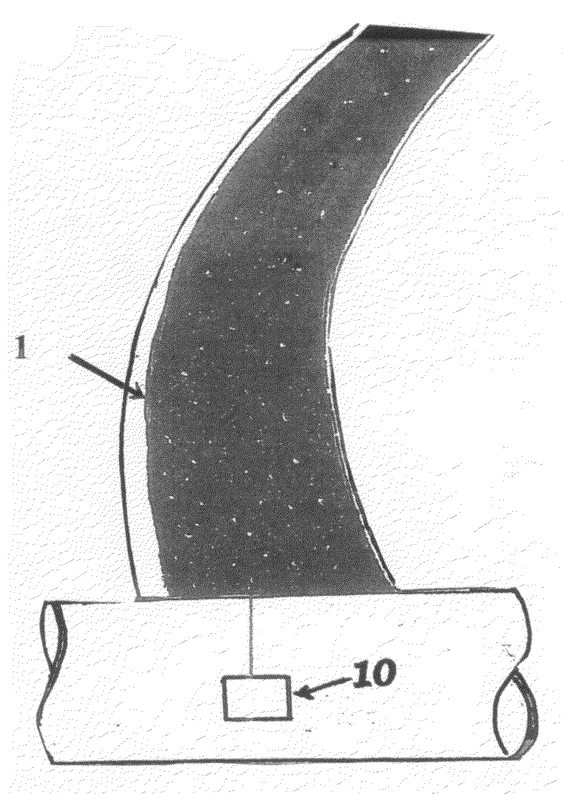
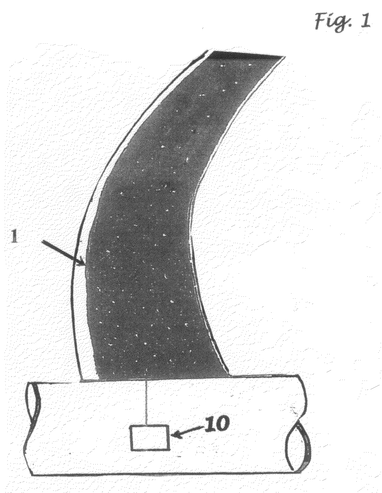
[0026]But turn the airplane is exactly what the present invention intends to do. In fact, it intends to control aerobatically any device that mimics the functionality and usefulness of an airplane. Better yet, the present inventor intends to effectively fill each micro-opening in a microperforated airfoil with a micro-robotic valve that, on command, will regulate vacuum suction or fluid injection so precisely that a wing which is covered with such an airfoil will be able to defeat surface or near-surface turbulence effects as they arise, no matter how small, particularly if sensing elements embedded in airfoils provide pressure and air speed infor

Problems solved by technology

The use of thicker, layerized airfoil skin materials up to 10 cm thick will not accommodate all wing and other

Method used


Image

  • Controlling aircraft aerial movements, defeating icing on aircraft surfaces, aiding decontamination, and damping turbulence effects on aircraft by the method of micro-perforated airfoil coordinated precision flow management
  • Controlling aircraft aerial movements, defeating icing on aircraft surfaces, aiding decontamination, and damping turbulence effects on aircraft by the method of micro-perforated airfoil coordinated precision flow management
  • Controlling aircraft aerial movements, defeating icing on aircraft surfaces, aiding decontamination, and damping turbulence effects on aircraft by the method of micro-perforated airfoil coordinated precision flow management

Examples


Embodiment Construction

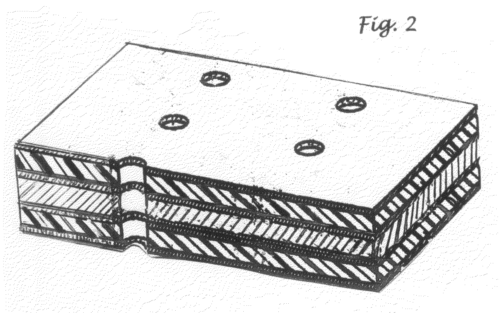
[0054]The plurality of microvalve necessary to this invention will be based on variations of one simple design. At the core of the valve will be a plunging needle filament element shaped rather like an inverted golf tee of from one micron to ten centimeters in length. In closed position the tip of the tee will normally extend up to the plane of the exterior airfoil surface in which suitable perforations have been provided. It may extend past this plane for special purposes, like de-icing, cleaning, or to deliberately cause a particular type of eddy current in a specific local region.

[0055]The diameter of the surface micro-opening through which the microvalve will reach or protrude slightly will be from one micron to 250 microns. The diameter of the microvalve head at its wide point on the inside surface of the skin will be from 100 microns to 5 mm.

[0056]When the plunging needle filament element retracts into the microperforation, powered by either or both a tension force applied to ...


PUM


Abstract

A method is provided whereby airplanes or any device with the functionality and usefulness of an airplane may be controlled without the use of any traditional effectors, such as flaps, rudders, ailerons, spoilers, and all like hinged, moveable airfoils attached to a wing or a fuselage. The means of controlling such airplanes while in flight will be by controlling the laminar air flow over all lifting surfaces so as to vary the amount and quality of the lift provided. All lifting surfaces on the airplane will be divided into dozens, hundreds, or thousands of small zones, each of which can be readily controlled by a central flight computer and each of which is capable of modifying its immediate airflow condition, whether that be laminar flow or some particular degree and variety of local eddy current. Summing over all the inputs of conditions above the multitude of zones, the central flight computer will possess algorithms and programs suitable to effect any desired change in attitude, altitude, orientation, and course of the airplane that is desired.

Description

CROSS-REFERENCE TO RELATED APPLICATION[0001]Related application Ser. No. 11 / 084,780 filed on Mar. 21, 2005. Provisional Application # 61 / 000,837 Filed Oct. 30, 2007FEDERALLY SPONSORED RESEARCHBACKGROUND OF THE INVENTION[0002]1. Prior Art[0003]This invention relates to a method of controlling the pitch, roll, and yaw of an airplane or any device with airplane-like functionality, without the use of either moveable effectors, space-vehicle style thrusters, or directed main engine thrust, by instead relying upon the precision management of volumes of air being sucked or blown through micro-holes, micro-slats, and micro-openings of any shape distributed in any pattern of sufficient density over an airfoil surface, which precision of flow management is so precise, timely, and efficacious that local flow conditions over an airfoil can be minutely adjusted so as to control any device with airplane-like functionality and usefulness, defeat icing, cool surfaces of the aircraft being aerodynam...

Claims


Application Information

Patent Timeline
IPC IPC(8): G06F17/00B64C21/10
CPCB64C21/025B64C23/005B64C2230/22B64C2230/06B64C2230/04Y02T50/166Y02T50/10
Inventor COOK, MICHAEL LEON
Owner COOK MR MICHAEL
Why Eureka
Try Eureka