Liquid manure spreading apparatus

Active Publication Date: 2009-08-27
MANDERS WALTER J A +1
View PDF49 Cites 5 Cited by
  • Summary
  • Abstract
  • Description
  • Claims
  • Application Information

AI Technical Summary

Benefits of technology

[0022]Preferably, the boom has a greater width than 10 feet and the hose has a length greater than 700 feet. The boom height is adjustable for crops as high as 4 feet. The adjustable boom height allows for the application of waste material throughout the growing season without the risk of damage to the tops of the plants from the machine. Multiple applications of waste material to the crop throughout the growing season has several advantages, growth is promoted by providing nutrients throughout the growing season, multiple applications of waste material increases the amount of material that can be disposed of in a s

Problems solved by technology

The use of a tank to distribute the slurry waste is basically unacceptable for larger quantities of the material in view of the very heavy weights of such a large

Method used


Image

  • Liquid manure spreading apparatus
  • Liquid manure spreading apparatus
  • Liquid manure spreading apparatus

Examples


Embodiment Construction

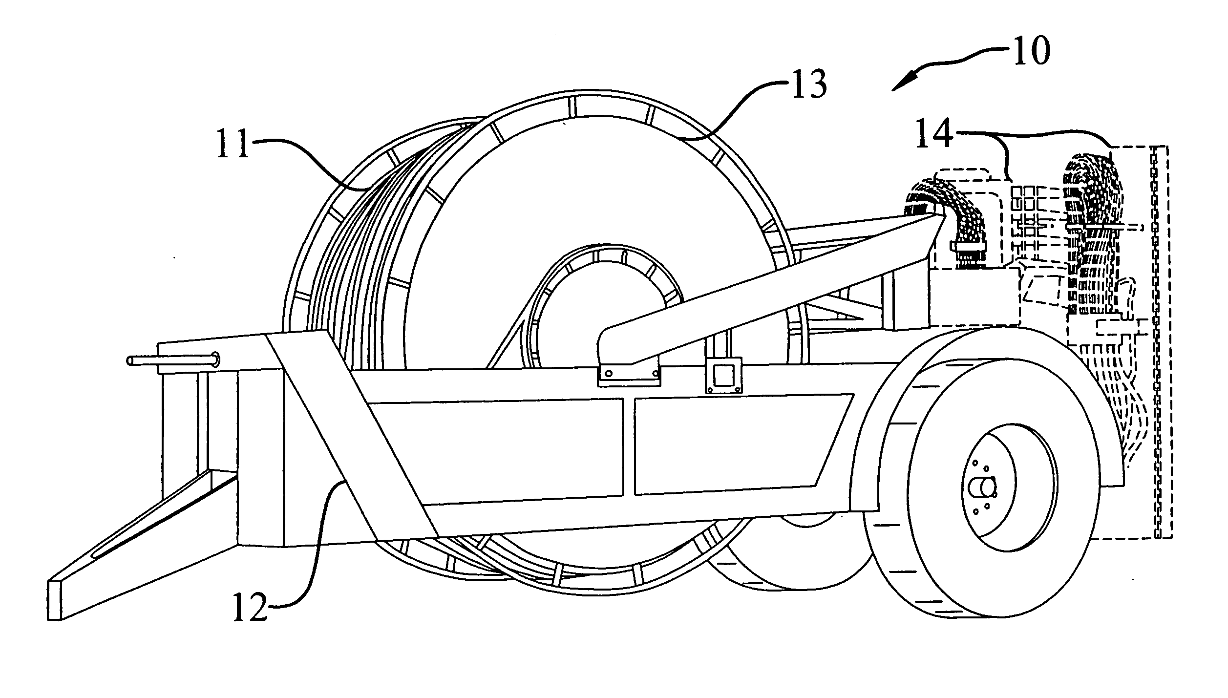
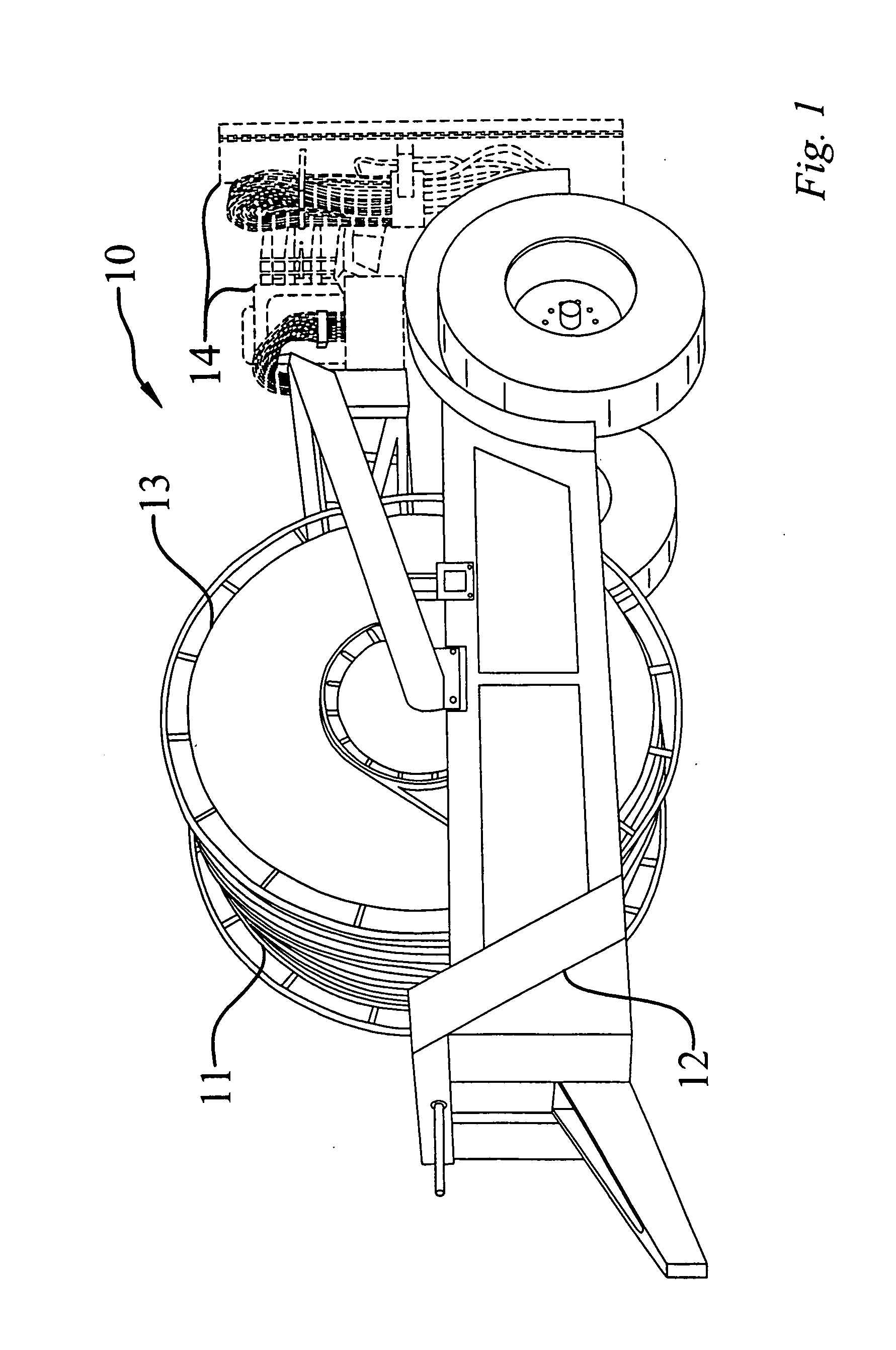
[0028]FIG. 1 shows the prior art hose dispensing system wherein the axis of the reel is perpendicular to the direction of travel and there is no hose dispensing boom. Element 10 is the device as a whole. Element 13 is the reel and 11 is the hose. Element 14 is the dispensing system for insertion of the waste material into the ground (not part of the present invention) and element 12 is the frame of the hose dispensing system.

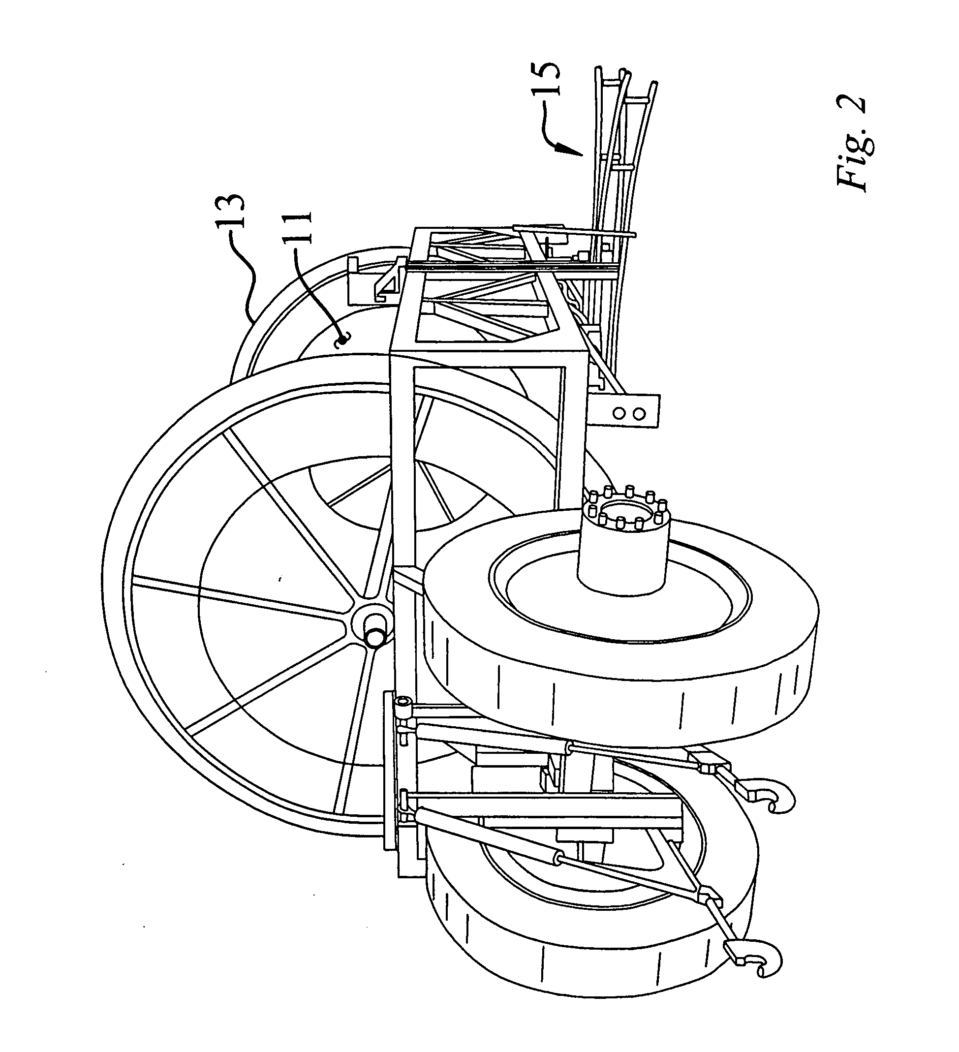
[0029]FIG. 2 is a perspective view of the present invention wherein element 11 is the hose and element 13 is the reel. Element 15 is the boom for dispensing and retrieval of the hose.

[0030]FIG. 3 is a detailed perspective of the hose dispensing boom wherein element 17 is a hose dispensing roller. The dispensing boom is connected to the frame of the system. This boom can be raised or lowered to accommodate the height of the crop.

[0031]The present invention is designed for enhanced application rates for slurry fertilizer, and operation at speeds in the range of 5 ...


PUM


Abstract

This invention is directed to a device for applying slurry manure beneath the soil or on top of the soil with reduced crop displacement by a trailing feeder hose. More specifically, the invention is directed to an improvement of the prior art slurry reel system. The slurry reel system of the present invention places the axis of the reel spool parallel with the direction of travel instead of the conventional perpendicular orientation. This invention also utilizes a unique hose placement and retrieval apparatus or boom.

Description

TECHNICAL FIELD[0001]This application relates to a device for applying slurry fertilizer beneath the soil or on top of the soil with reduced crop displacement by a trailing feeder hose. More specifically, the present invention is directed to an improvement of the prior art slurry reel system. The slurry reel system of the present invention places the axis of the reel spool parallel with the direction of travel instead of the conventional perpendicular orientation. This invention also utilizes a unique hose placement and retrieval apparatus.BACKGROUND OF THE INVENTION[0002]The present invention relates to agricultural fertilizer applicators. Particularly, it relates to an apparatus for application of livestock waste in the form of slurry (that is, a freely flowing mixture of liquids and solids). Historically, livestock waste, particularly in solid form, has been spread on the surface of the soil by a manure spreader using a flail to fling the material to the rear. A more modern side-...

Claims


Application Information

Patent Timeline
IPC IPC(8): A01C23/00A01C21/00C09K17/14
CPCA01C23/021
Inventor MANDERS, WALTERMANDERS, HEIN
Owner MANDERS WALTER J A
Why Eureka
Try Eureka