Reflector element for a solar heat reflector and the method for producing the same

a solar heat reflector and reflector element technology, applied in the field of reflector elements, can solve the problems of sun energy reflection loss, optical deficiencies, environmental concerns, etc., and achieve the effect of preventing water salt pollution deposits on glass surfaces and preventing glass from stress breaking

Inactive Publication Date: 2009-08-27
RIOGLASS SOLAR
View PDF7 Cites 10 Cited by
  • Summary
  • Abstract
  • Description
  • Claims
  • Application Information

AI Technical Summary

Benefits of technology

[0024]In this sense a ‘self-supported’ glass pane shall be understood throughout this document as a glass pane which does not require the cooperation of a frame member or any other device to maintain its shape at the normal utilization temperatures, and that it is kept in its working position by the supporting structure. The absence of a frame member or other device in the reflector element of the invention to keep its curved shape results in material, money and time saving in its manufacturing and also has the advantage of a smaller weight and maintenance cost of the solar heat reflector.
[0042]Glass handling is made with special automatic or manual devices that allow easy displacement when loading and unloading operations are carried out.

Problems solved by technology

The dependence on these non-renewable exhaustible fuels raises environmental concerns and is a source of regional and global conflicts.
As the need for energy grows and the reserves of fossil fuels are being depleted, governments all over the world are facing the challenge of establishing initiatives to develop efficient renewable energy technologies for the use and production of energy obtained from natural sources such us wind, sunlight, tides, waves or geothermal heat.
A drawback of a parabolic reflector thus produced is that the hot-bending may cause some distortions which lead to optical deficiencies and sun energy reflection loss.
Other drawbacks are the low bent glass production rate achieved when using this manufacturing methodology and the low resistance of the glass panes to the wind loads and the accidental impacts against them.
The method set forth in said documents has some limitations and drawbacks, among which:The glass substrate must necessarily be sufficiently flexible to be cold-bent, said flexibility being usually provided by making a relatively thin glass substrate.As abovementioned, parabolic reflectors produced by this method need to be maintained in their bent shape by a frame member, otherwise they would recover their flat shape.
In that case a flexible glass substrate is included in a laminate with a metal ply and the laminate is subjected to flexing forces, causing its flexure within the elastic limit of the metal ply.
This method of chemical tempering is time-demanding, low manufacturing rated and very expensive.
However, this glass can become fragile when exposed to wind loads, impact of solids in the open air and when be provided with bores it cannot bear the necessary mounting or fixing stresses.

Method used


Image

  • Reflector element for a solar heat reflector and the method for producing the same
  • Reflector element for a solar heat reflector and the method for producing the same
  • Reflector element for a solar heat reflector and the method for producing the same

Examples


Embodiment Construction

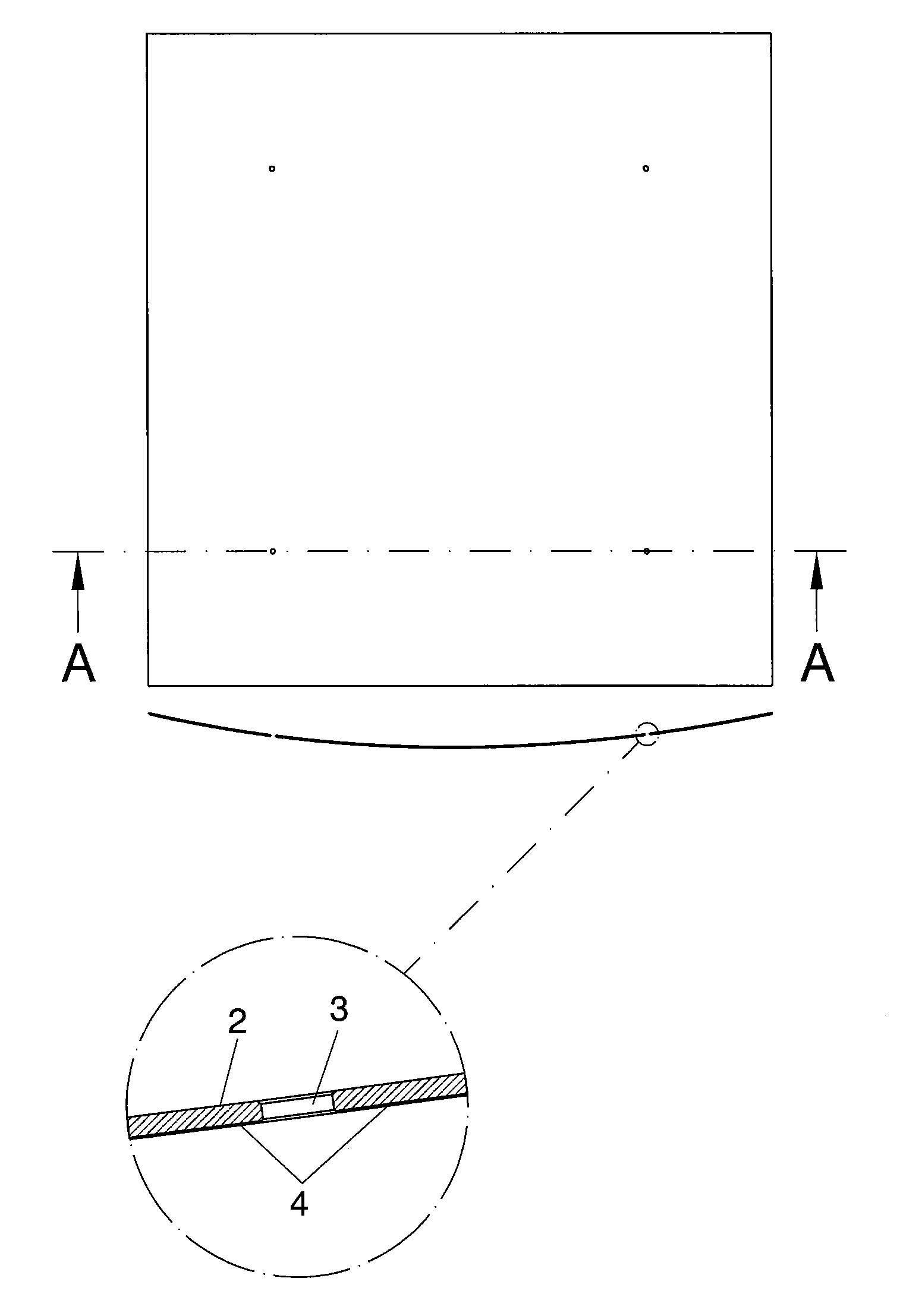
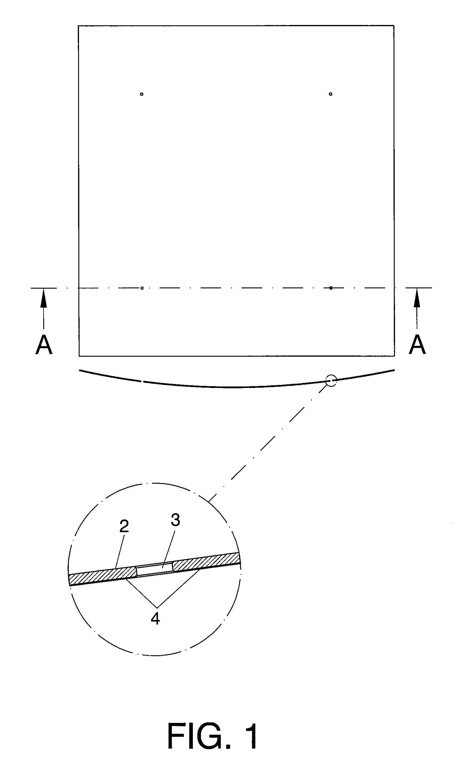
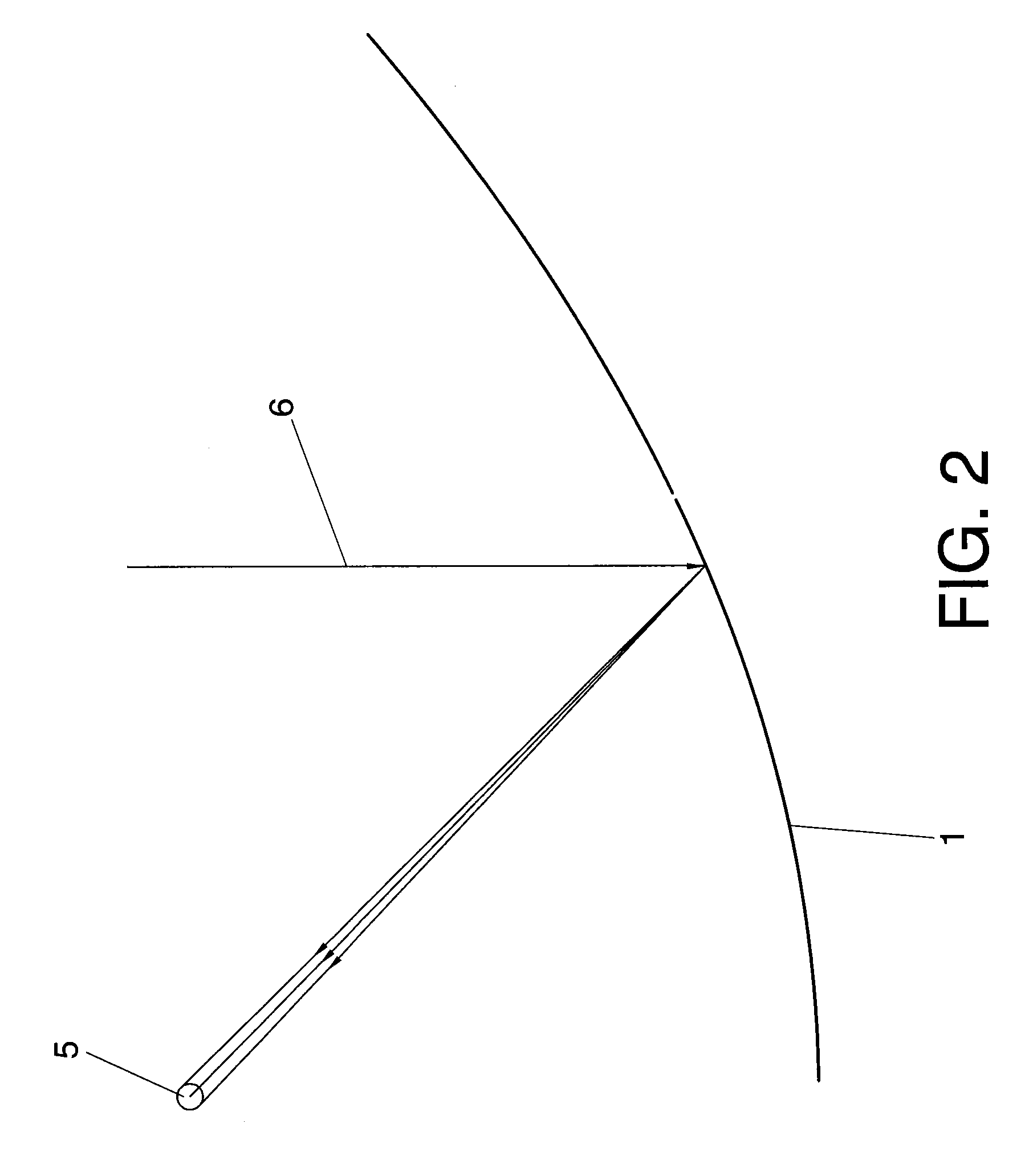
[0055]In FIG. 1 a reflector element (1) for a solar collector according to a preferred embodiment of the invention is shown in both, top and side—section AA—views. Said reflector element comprises a not mechanically flexed monolithic glass pane (2) of heat treated glass which due to its enhanced resistance properties becomes self-supported without requiring the presence of any kind of frame member or device to maintain its shape at the normal utilization temperatures. The principle of reflection of an incident solar ray (6) in a reflector element (1) and the corresponding absorbing tube (5) is shown in FIG. 2.

[0056]In an embodiment the thickness of the glass pane is equal or less than 5 mm.

[0057]FIG. 3 shows the reflector element (1) of the invention and a detail of a conventional mounting means (7) for fixing the reflector element (1) to a solar heat reflector's structure. These conventional mounting means (7), which do not require bores in the reflector, comprises supporting pads ...


PUM


Abstract

Reflector element (1) for a solar collector which comprises a not mechanically flexed monolithic glass pane (2) of heat treated glass which due to its enhanced resistance properties becomes self-supported without requiring the presence of any kind of frame member or device to maintain its shape at the normal utilization temperatures. The reflector element is substantially parabolic and can be provided with at least one bore (3) for a fixing element to fix the reflector element (1) to a supporting structure.

Description

TECHNICAL FIELD[0001]The present invention relates to a reflector element for use in a solar heat reflector or the like, a solar heat reflector comprising at least one of those reflector elements, a solar heat reflecting installation comprising at least one those solar reflectors, and to a method of manufacturing the reflector element.DESCRIPTION OF RELATED ART[0002]Technologically advanced societies have become increasingly dependent on energy. As populations and living standards rise, the demand for energy grows and this trend will continue in the future. Consequently, the capability of a nation to satisfy its energy need plays a crucial role in its economic output and in its inhabitants' quality of life. Fossil fuels are currently the most used energy resources. The dependence on these non-renewable exhaustible fuels raises environmental concerns and is a source of regional and global conflicts.[0003]As the need for energy grows and the reserves of fossil fuels are being depleted...

Claims


Application Information

Patent Timeline
Patent Type & Authority Applications(United States)
IPC IPC(8): F24J2/12B05D5/06F24S23/70F24S23/71F24S23/74
CPCF24J2/1057F24J2/14F24J2/5243G02B7/183Y02E10/45G02B5/10F24S23/82F24S23/74F24S25/60Y02E10/40
Inventor GARCIA-CONDE NORIEGA, IGNACIOUBACH CARTATEGUI, JOSEP
Owner RIOGLASS SOLAR
Why Eureka
Try Eureka