Super-thin water jetting lance

a water jetting lance and super-thin technology, applied in the direction of steam boiler components, cleaning heat-transfer devices, cleaning using liquids, etc., can solve the problems of affecting the efficiency of the generator, the reliability figures have not been proved, and the tubes to degrade, so as to maximize the hydraulic pressure, facilitate operation, and improve the effect of cleaning

Inactive Publication Date: 2009-08-27
FOSTER-MILLER
View PDF27 Cites 31 Cited by
  • Summary
  • Abstract
  • Description
  • Claims
  • Application Information

AI Technical Summary

Benefits of technology

[0013]It is a further object of this invention to provide a super-thin water jetting lance which makes it possible to access steam generator inter-tube gaps that conventional and commercially available lances cannot access because of geometrical limitations.
[0014]It is a further object of this invention to provide such a cleaning / inspection lance which is reliable, easy to operate, and efficient.
[0015]It is a further object of this invention to provide a steam generator cleaning system which maximizes hydraulic pressure for more effective cleaning.
[0016]It is a further object of this invention to provide such a system with fewer components for increased reliability.

Problems solved by technology

Steam generators were designed to last upwards of forty years but in practice such reliability figures have proven not to be the case.
The problem is that sludge from particulate impurities suspended in the feed-water forms on the tubes which greatly affects the efficiency of the generator and can even cause the tubes to degrade to the point of causing fissures in the tubes.
If radioactive primary fluid within the tubes seeps into the secondary side, the result can be disastrous.
Plugging or otherwise servicing such fissures is time consuming and results in expensive down time during which power must be purchased from other sources at a great expense.
Chemical cleaning is very expensive (from $5,000,000 to $10,000,000 per application) and requires an extended outage.
Also, some corrosion of steam generator internals by the solvents used will occur during the cleaning.
In addition, large quantities of hazardous, possibly radioactive waste may be generated.
Disposal of this waste is very expensive.
For these reasons, few plants have actually implemented chemical cleaning.
On the other hand, there are severe technical challenges faced when considering such alternate cleaning methods.
In some steam generators, however, such as the model CE-80 design, the blow down lane or “no-tube lane” along the tube sheet is very restrictive because a thick divider plate splits the hand hole opening, providing limited access (less than 1.35 inches) on either side and the inter-tube gap may not exceed 0.116 inches.
A typical flexible lance transporter is too large to enter such a blow down or no-tube lane in these steam generators and conventional lances are too thick to enter the small tube gaps and do any meaningful work.

Method used


Image

  • Super-thin water jetting lance
  • Super-thin water jetting lance
  • Super-thin water jetting lance

Examples


Embodiment Construction

[0042]Aside from the preferred embodiment or embodiments disclosed below, this invention is capable of other embodiments and of being practiced or being carried out in various ways. Thus, it is to be understood that the invention is not limited in its application to the details of construction and the arrangements of components set forth in the following description or illustrated in the drawings. If only one embodiment is described herein, the claims hereof are not to be limited to that embodiment. Moreover, the claims hereof are not to be read restrictively unless there is clear and convincing evidence manifesting a certain exclusion, restriction, or disclaimer.

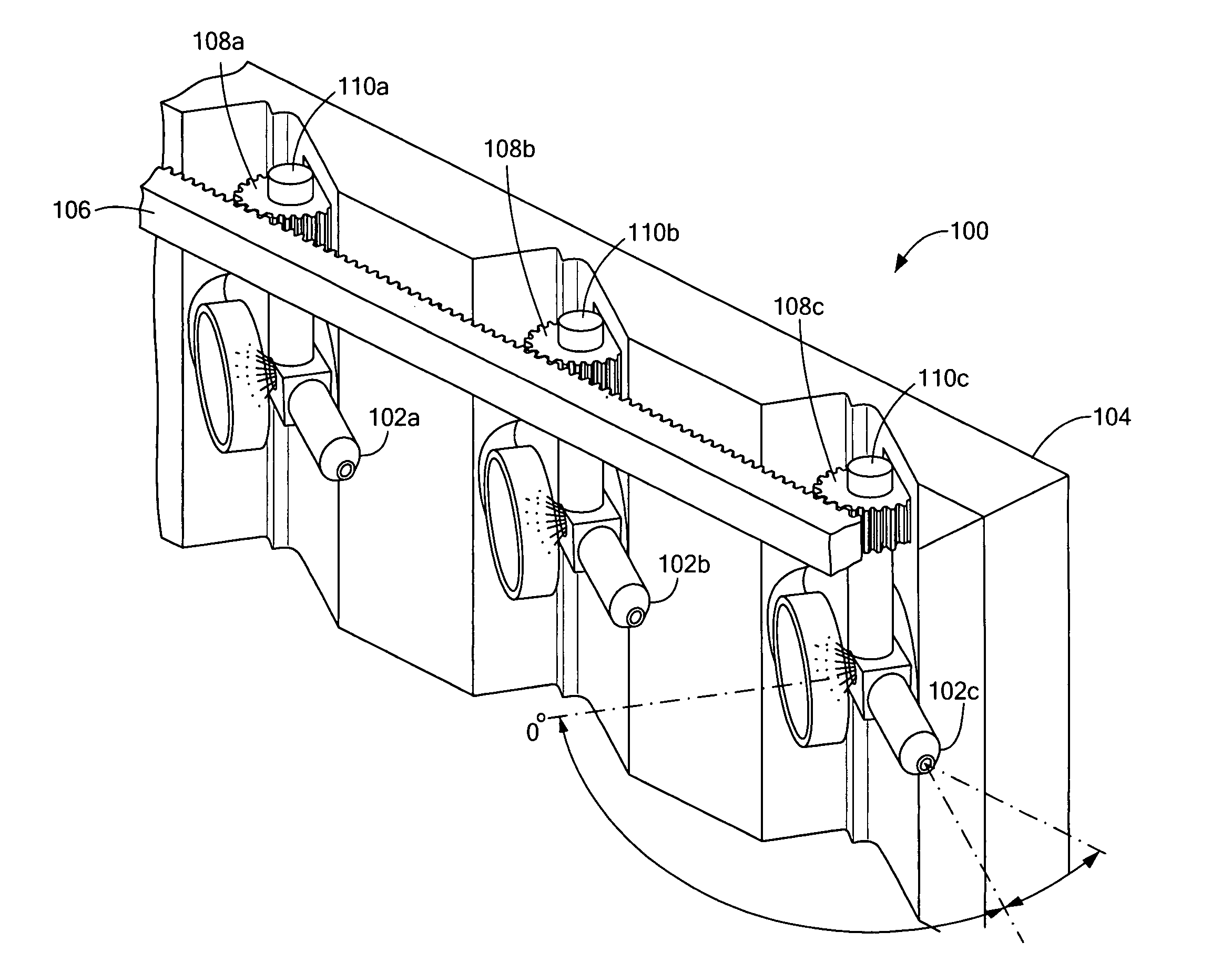
[0043]A super-thin water jetting lance in accordance with the subject invention makes it possible to access steam generator inter-tube gaps where conventional or other commercially available lances cannot access because of geometrical limitations.

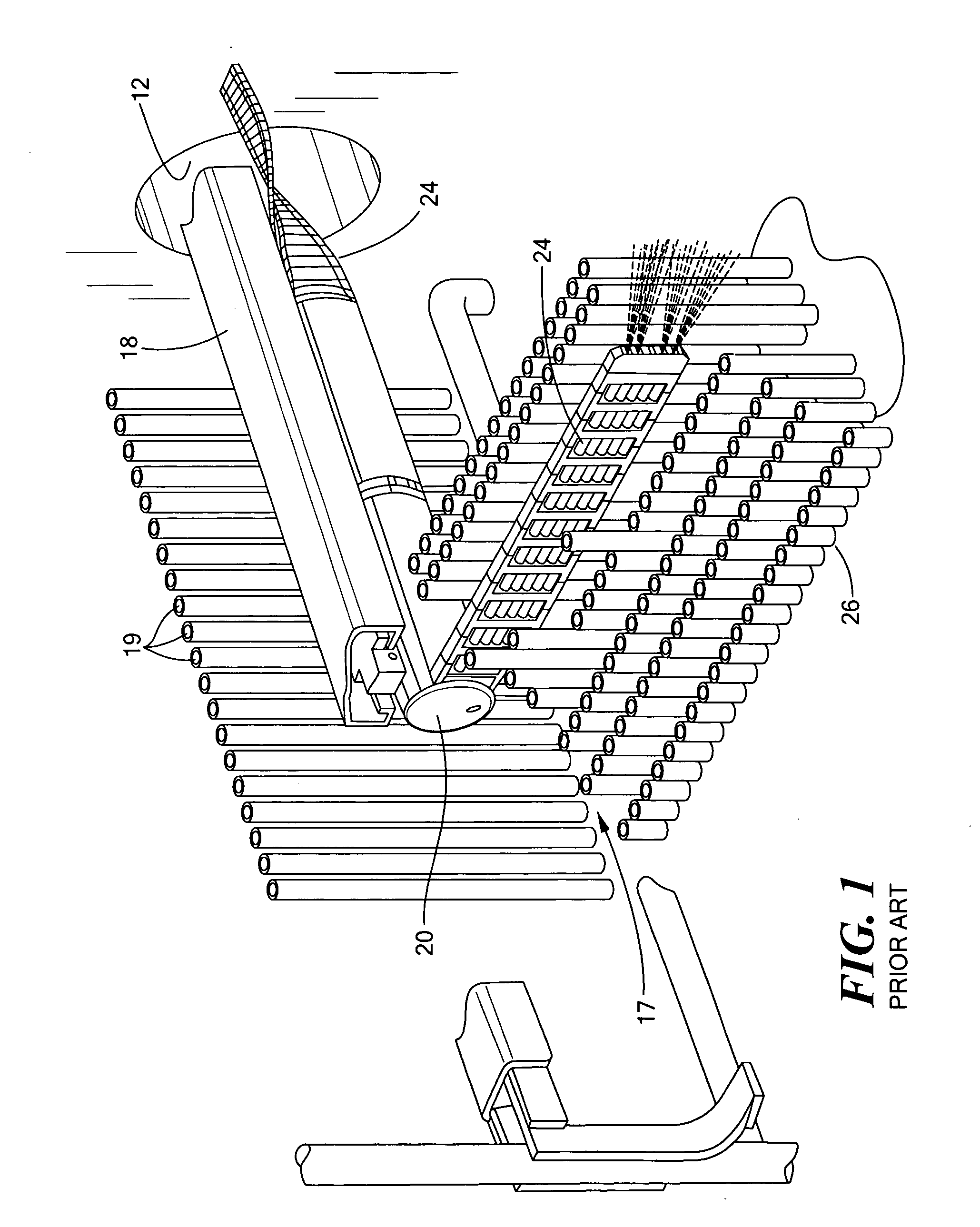
[0044]Commercially available equipment was designed to access steam generator ...


PUM


Abstract

A steam generator lance configured as a stack of adjacent tubes in a single column. The tubes are secured at least some locations. The lance includes a distal end with tube nozzles. A mechanism is provided for positioning the distal end of the lance into a tube lane. There is typically another mechanism for driving the lance so that the distal end thereof enters the tube lane.

Description

RELATED APPLICATIONS[0001]This application hereby claims the benefit of and priority to U.S. Provisional Application Ser. No. 61 / 010,340, filed on Jan. 8, 2008 under 35 U.S.C. §§119, 120, 363, 365, and 37 C.F.R. §1.55 and §1.78.FIELD OF THE INVENTION[0002]The subject invention relates to cleaning and inspection systems used within steam generators.BACKGROUND OF THE INVENTION[0003]Steam generators convert heat from the primary side of a pressurized water reactor type nuclear power plant to steam on the secondary side so that the primary and secondary systems are kept separate. A typical generator is a vertical cylinder consisting of a larger number of U-shaped tubes which extend from the floor or “tube sheet” of the generator upwards. High temperature and pressure fluid from the reactor travels through the tubes giving up energy to a feed water blanket surrounding the tubes in the generator creating steam and ultimately power when later introduced to turbines.[0004]Steam generators w...

Claims


Application Information

Patent Timeline
Patent Type & Authority Applications(United States)
IPC IPC(8): B08B3/02
CPCB08B3/024B08B9/023F28G15/04F22B37/483F28G1/166F22B37/005
Inventor ATHANASSIU, CHRISTOSVALENTINE, JR., JOSEPH WILLIAMOSBORNE, MICHAEL W.KANAAN, ABED
Owner FOSTER-MILLER
Why Eureka
Try Eureka