Touch panel

a technology of touch panel and conductive film, which is applied in the field of touch panel, can solve the problems of inferior flexibility to sharply raise electrical resistance, prone to cracking of ito conductive film b>112/b> and b>122/b>, and comparatively limited operation life, so as to avoid drifting to linear response, reduce surface resistivity, and improve electrical conductivity

Inactive Publication Date: 2009-08-27
WINTEK CORP
View PDF3 Cites 15 Cited by
  • Summary
  • Abstract
  • Description
  • Claims
  • Application Information

AI Technical Summary

Benefits of technology

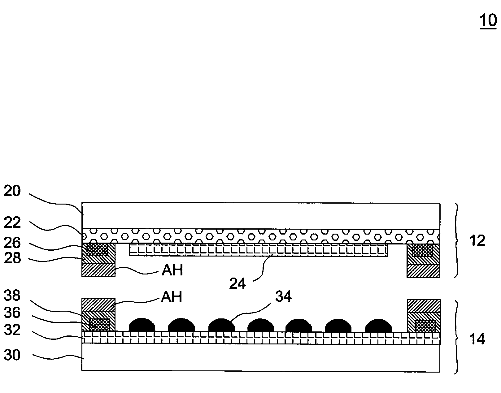
[0016]According to the above embodiments, a transparent conductive composite that includes both a polymeric conductive film and a non-polymeric conductive film serves as a conductive layer for the touch screen of a touch panel. Hence, on one hand, the non-polymeric conductive film allows to improve electrical conductivity and reduce surface resistivity, with these characteristics being inherently inferior in a polymeric conductive film, to avoid a drift to the linear response when one draws a line on the touch screen of a touch panel. On the other hand, even the non-polymeric conductive film splits or cracks through repetitive drawing, the polymeric conductive film that has competent flexibility allows to maintain electrical conduction and thus increase the bearable number of times for drawing a line on a touch screen.

Problems solved by technology

However, under a critical condition where surface resistivity reaches 500 ohm, its bearable number of times for drawing a line on a touch screen is not allowed to exceed 50,000 to result in a comparatively limited operation life.
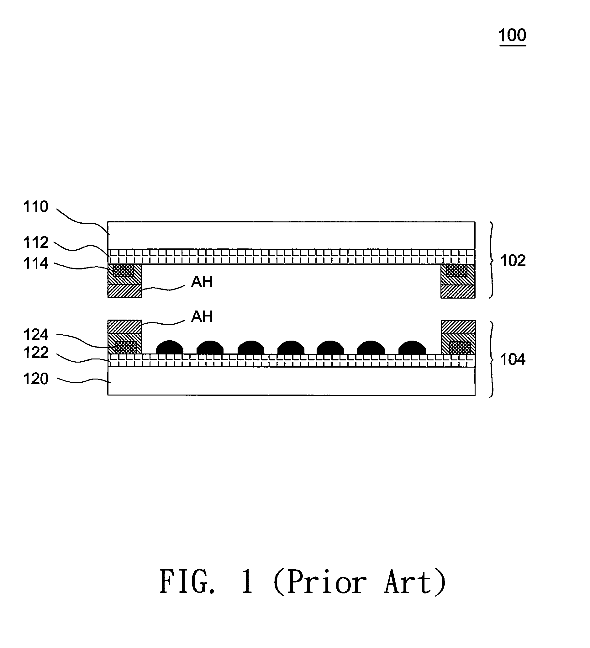
Besides, the ITO conductive films 112 and 122 are prone to crack upon bending due to their inferior flexibility to sharply raise electrical resistances.
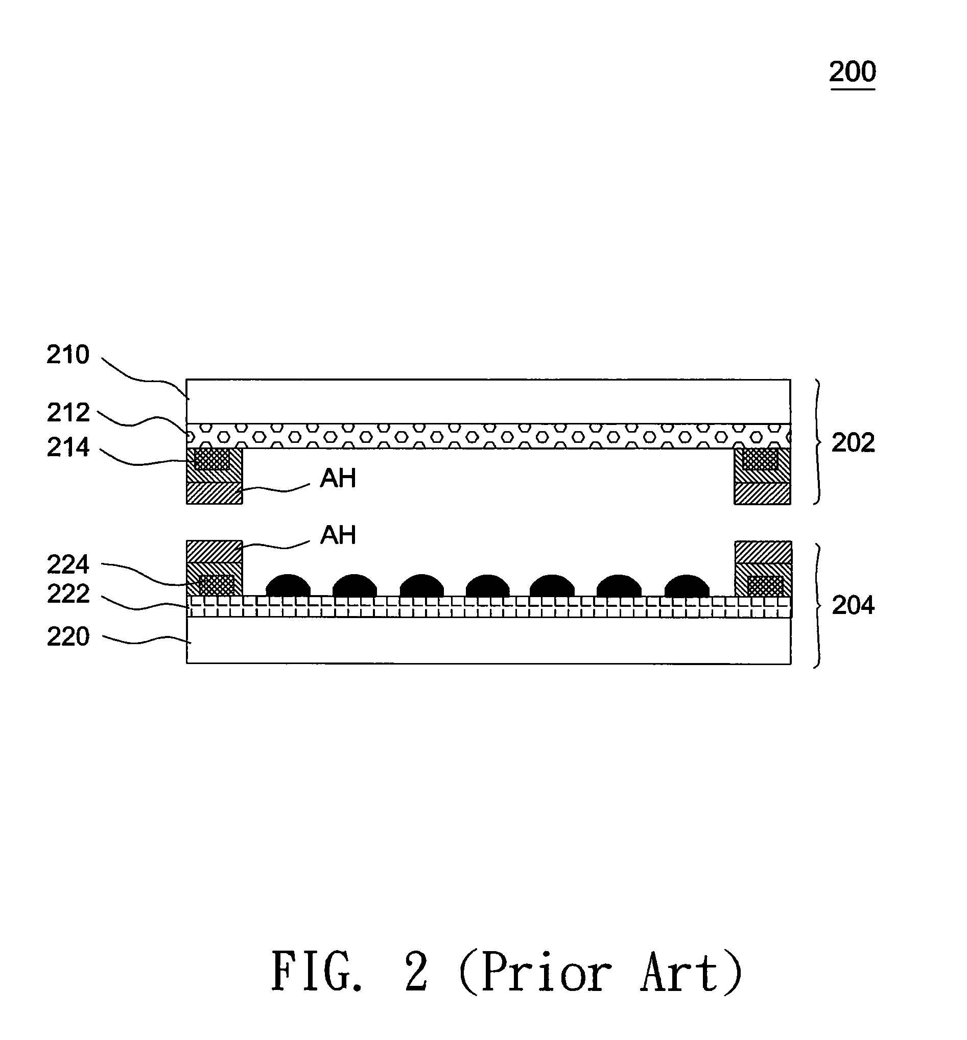
However, the polymeric conductive film 212 has inferior electrical conductivity and high surface resistivity, which often cause inferior reliability and a drift to the linear response when one draws a line on the touch screen.

Method used


Image

  • Touch panel
  • Touch panel
  • Touch panel

Examples


Embodiment Construction

[0022]In the following detailed description of the preferred embodiments, reference is made to the accompanying drawings which form a part hereof, and in which are shown by way of illustration specific embodiments in which the invention may be practiced. In this regard, directional terminology, such as “top,”“bottom,”“front,”“back,” etc., is used with reference to the orientation of the Figure(s) being described. The components of the present invention can be positioned in a number of different orientations. As such, the directional terminology is used for purposes of illustration and is in no way limiting. On the other hand, the drawings are only schematic and the sizes of components may be exaggerated for clarity. It is to be understood that other embodiments may be utilized and structural changes may be made without departing from the scope of the present invention. Also, it is to be understood that the phraseology and terminology used herein are for the purpose of description an...


PUM


Abstract

A touch panel includes a first and a second transparent substrates, a first and a second signal lines, a first polymeric conductive film, and a first and a second non-polymeric conductive films. The first signal line is formed on the first transparent substrate, the first polymeric conductive film is formed on the first transparent substrate, and the first non-polymeric conductive film is formed on the first polymeric conductive film. The second signal line is provided on the second transparent substrate, and the second non-polymeric conductive film is provided on the second transparent substrate.

Description

CROSS REFERENCE TO RELATED APPLICATION[0001]This application claims benefit of U.S. provisional application No. 61 / 031,408 filed on Feb. 26, 2008 under 35 U.S.C. § 119(e); the entire contents of which are hereby incorporated by reference.BACKGROUND OF THE INVENTION[0002]1. Field of the Invention[0003]The invention relates to a touch panel, particularly to a touch panel having transparent conductive films with excellent physical characteristics.[0004]2. Description of the Related Art[0005]FIG. 1 shows a schematic diagram of a conventional touch panel 100. Referring to FIG. 1, the touch panel 100 includes a top electrode substrate 102 and a bottom electrode substrate 104 facing to each other. The top electrode substrate 102 includes a transparent substrate 110, an ITO conductive film 112 formed on the transparent substrate 110, and signal transmission lines 114. The bottom electrode substrate 104 includes a transparent substrate 120, an ITO conductive film 122 formed on the transparen...

Claims


Application Information

Patent Timeline
Patent Type & Authority Applications(United States)
IPC IPC(8): G06F3/041
CPCG06F3/045
Inventor WANG, CHIH-YUANCHOU, CHENG-YILI, JYUN-SIAN
Owner WINTEK CORP
Why Eureka
Try Eureka