Transponder back scatter modulator with regulated modulation depth

a back scatter modulator and transponder technology, applied in the field of rfid transponders, to achieve the effect of precise and constant modulation depth and precise regulation of antenna voltag

Inactive Publication Date: 2009-08-27
TEXAS INSTR INC
View PDF9 Cites 4 Cited by
  • Summary
  • Abstract
  • Description
  • Claims
  • Application Information

AI Technical Summary

Benefits of technology

[0005]It is a general object of the present invention to provide an RFID transponder in which a precise modulation of the back scatter load can be achieved.
[0006]This and other objects and features are provided, in accordance with an aspect of the present invention provides an RFID transponder including an antenna and modulation circuitry for back scatter modulation at a local voltage rail connected to the antenna such that a voltage of the antenna is maintained within a predetermined range. The modulation circuitry includes a voltage regulation loop including a rectifier connected between the antenna and the local voltage rail for rectifying a voltage from the antenna so as to load the local voltage rail with the rectified voltage from the antenna. There is an error amplifier for comparing a voltage at the local voltage rail with a modulation voltage and producing an output signal. A switch is provided for switching the modulation voltage between a first reference voltage level and a second reference voltage level. A regulated load is coupled between the output of the error amplifier and the antenna, which is varied in response to the error amplifier output signal. Basically, this provides a regulated load to the antenna, which is controlled on the basis of a data stream to be transmitted using, for example, amplitude shift keying (ASK). The error amplifier compares the antenna voltage with the modulation voltage level, which is derived either from the first reference voltage level or the second reference voltage level. The resultant output voltage of the amplifier is used to control the voltage at the local voltage rail so that it complies with the modulation voltage. In order to obtain the required modulation depth, the first and second reference voltage levels can be adjusted. If the second reference voltage is greater than the first reference voltage level and the second reference voltage is connected to the error amplifier via the switch, then only minor or no additional damping occurs. If the first reference level is used as modulation voltage, the antenna voltage will be pulled down with the regulated load until the local voltage rail is equal to the reference voltage level. The back scatter modulation circuitry is therefore able to work with a dramatically reduced antenna limiter threshold and the modulation depth is controlled by a voltage regulation loop so that a precise and constant modulation depth is achieved independently of the field strength. Since a precise regulation of the antenna voltage can be obtained even at low antenna and supply voltages, the modulation circuitry of the present invention can easily be implemented in a deep sub-micron process.
[0009]An aspect of the present invention also provides a method of modulating backscatter in an RFID transponder. A rectified voltage level of an antenna at a local voltage rail is monitored and a difference of the rectified voltage level with a modulation voltage level is determined. Then the modulation voltage level is varied between a first reference voltage level and a second reference voltage level in accordance with data to be transmitted. Finally, a load coupled to the antenna is controlled, in a way so as to increase or decrease the load based on the determined difference between the modulation voltage level and the rectified antenna voltage until the rectified voltage level is equal to the modulation voltage level. The method according to the invention achieves regulation of the voltage at the antenna and thus modulates the backscatter at the antenna. The method of back scatter modulation of the present invention is able to work with a dramatically reduced antenna limiter threshold and controls the modulation depth by a voltage regulation loop so that a precise and constant modulation depth is achieved independently of the field strength. The modulation depth can be adjusted by adjusting the reference voltage levels. A precise regulation of the antenna voltage can be obtained even at low antenna and supply voltages, which provides the advantage that the method of the present invention can easily be used in a deep sub-micron process. If one of the reference voltage levels is the internal supply voltage, the regulated load can basically be turned off.

Problems solved by technology

There is an error amplifier for comparing a voltage at the local voltage rail with a modulation voltage and producing an output signal.

Method used


Image

  • Transponder back scatter modulator with regulated modulation depth
  • Transponder back scatter modulator with regulated modulation depth

Examples


Embodiment Construction

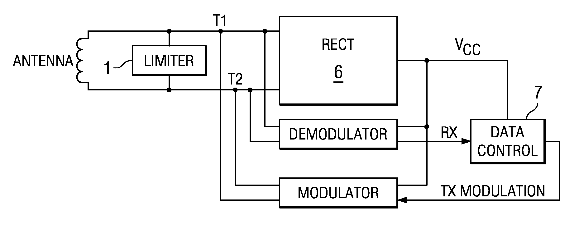
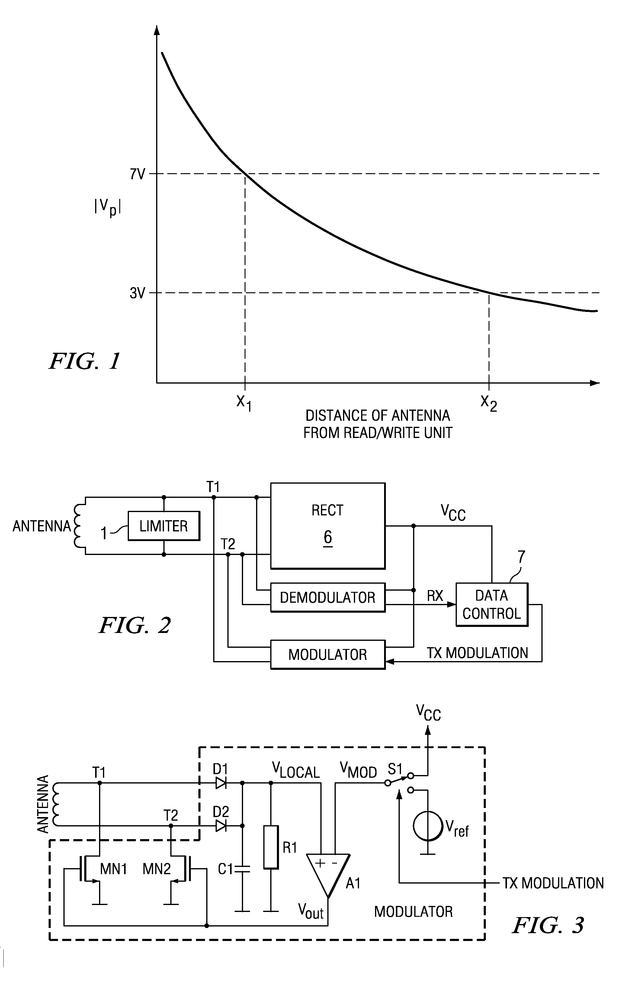
[0014]FIG. 1 is a graph of the magnitude of the peak transponder voltage as a function of the distance of the transponder from a read / write unit for an RFID transponder. The modulus (magnitude) of the peak voltage of RFID transponders as a function of the distance of the transponder (antenna) from the read / write (R / W) unit is shown in FIG. 1, with specific distances X1 and X2 being indicated for former and up-to-date transponders, respectively. For example, present devices are able to withstand voltages of up to 3V, whereas former designs used integrated circuits that were able to withstand 8V. The rectifier generates the supply of the whole transponder by rectifying the antenna voltage. The voltage drop over the rectifier, together with the reduced limiter threshold of 3V, results in a supply voltage of only about 2.5V when the maximum distance of the transponder away from the R / W unit X2 is 30 cm, for example, whereas former designs with a limiter threshold of 7V were able to oper...


PUM


Abstract

An RFID transponder includes an antenna and modulation circuitry for back scatter modulation at an local voltage rail connected to the antenna such that a voltage of the antenna is maintained within a predetermined range. The modulation circuitry includes a voltage regulation loop including a rectifier connected between the antenna and the local voltage rail (Vlocal) for rectifying a voltage from the antenna so as to load the local voltage rail (Vlocal) with the rectified voltage from the antenna, an error amplifier (A1) for comparing a voltage at the local voltage rail (Vlocal) with a modulation voltage (Vmod) and producing an output signal (Vout), a switch for switching the modulation voltage (Vmod) between a first reference voltage level (Vref) and a second reference voltage level, wherein a regulated load is coupled between the output of the error amplifier (A1) and the antenna, which is varied in response to the output signal (Vout).

Description

[0001]This application claims the benefit of application Ser. No. 60 / 016,764 filed on Dec. 26, 2003 which is incorporated in it's entirety by reference.FIELD OF THE INVENTION[0002]The present invention generally relates to an RFID transponder. More particularly, the present invention relates to an RFID transponder with back scatter modulation.BACKGROUND OF THE INVENTION[0003]RFID transponder circuits are widely used in many different applications and are becoming ever more reduced in size, due to finding popular applications in tagging and “electronic passports”. The received antenna voltage of an RFID transponder has to be limited in order to avoid damage due to electrical overstress. The threshold for the limitation is determined by the capabilities of the integrated circuit used in the transponder. Modern deep sub micron processes with a minimum gate length of, e.g. 130 nm or less, are needed for transponder design to integrate more functionality such as larger memories and highe...

Claims


Application Information

Patent Timeline
Patent Type & Authority Applications(United States)
IPC IPC(8): H04Q5/22
CPCG06K19/0723
Inventor GANZ, RUEDIGER
Owner TEXAS INSTR INC
Why Eureka
Try Eureka