Microscope System, Image Generating Method, and Program for Practising the Same

a microscope and image generating technology, applied in the field of microscope technology, can solve the problems of variation in examination accuracy, laborious work to screen a large number of malignant cells, etc., and achieve the effect of improving accuracy and efficiency of cytologic examination

Active Publication Date: 2009-08-27
EVIDENT CORP
View PDF12 Cites 81 Cited by
  • Summary
  • Abstract
  • Description
  • Claims
  • Application Information

AI Technical Summary

Benefits of technology

[0027]According to the present invention, by the above construction, it is possible that the accuracy

Problems solved by technology

It is very laborious work to screen a malignant cell from among a great number of cells.
The occurrence of a false negative case caused by an oversight for the malignant cell attributable to the fatigue and ability of the cytotechnologist

Method used


Image

  • Microscope System, Image Generating Method, and Program for Practising the Same
  • Microscope System, Image Generating Method, and Program for Practising the Same
  • Microscope System, Image Generating Method, and Program for Practising the Same

Examples


embodiment 1

Generation of Entire Specimen VS Image

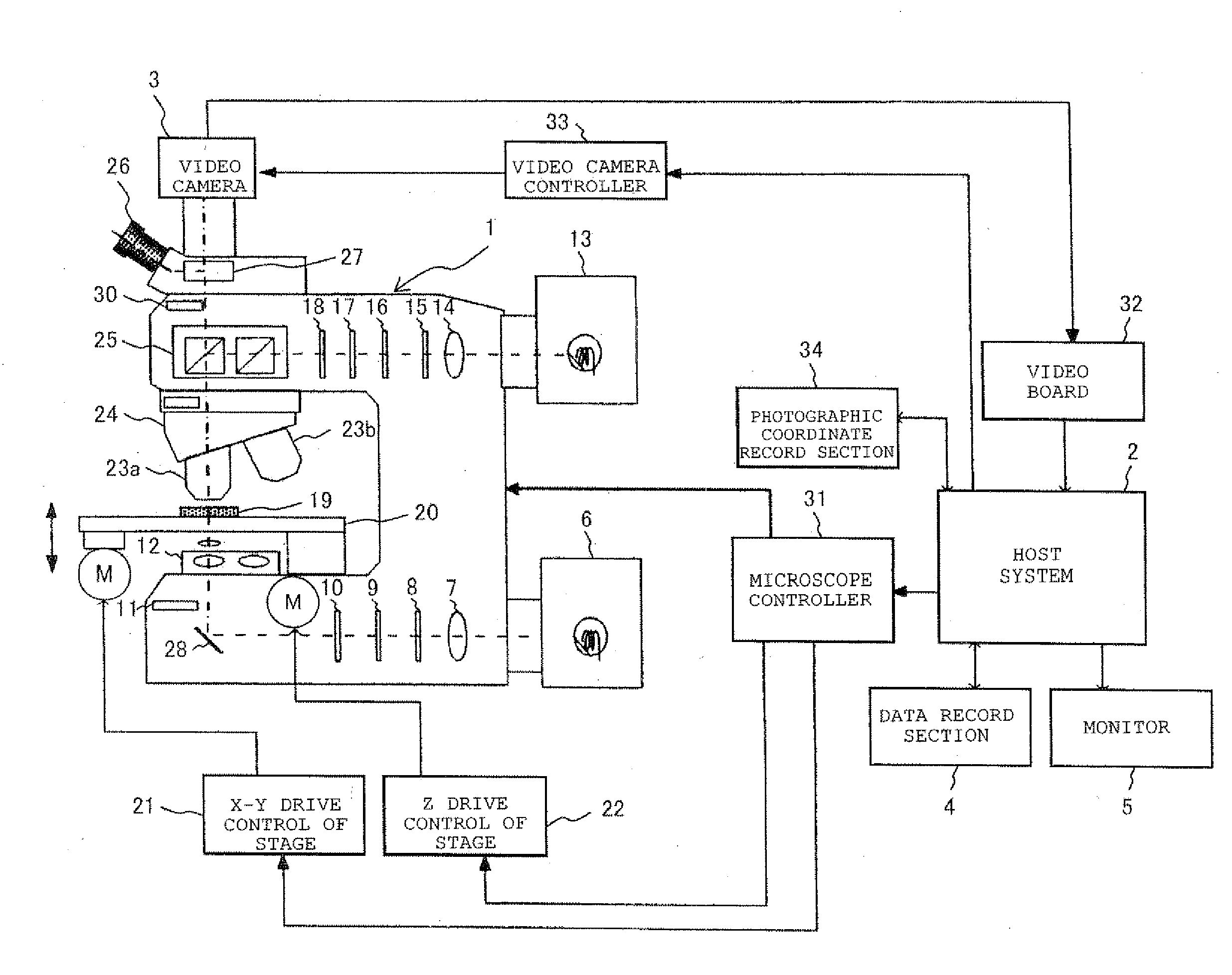
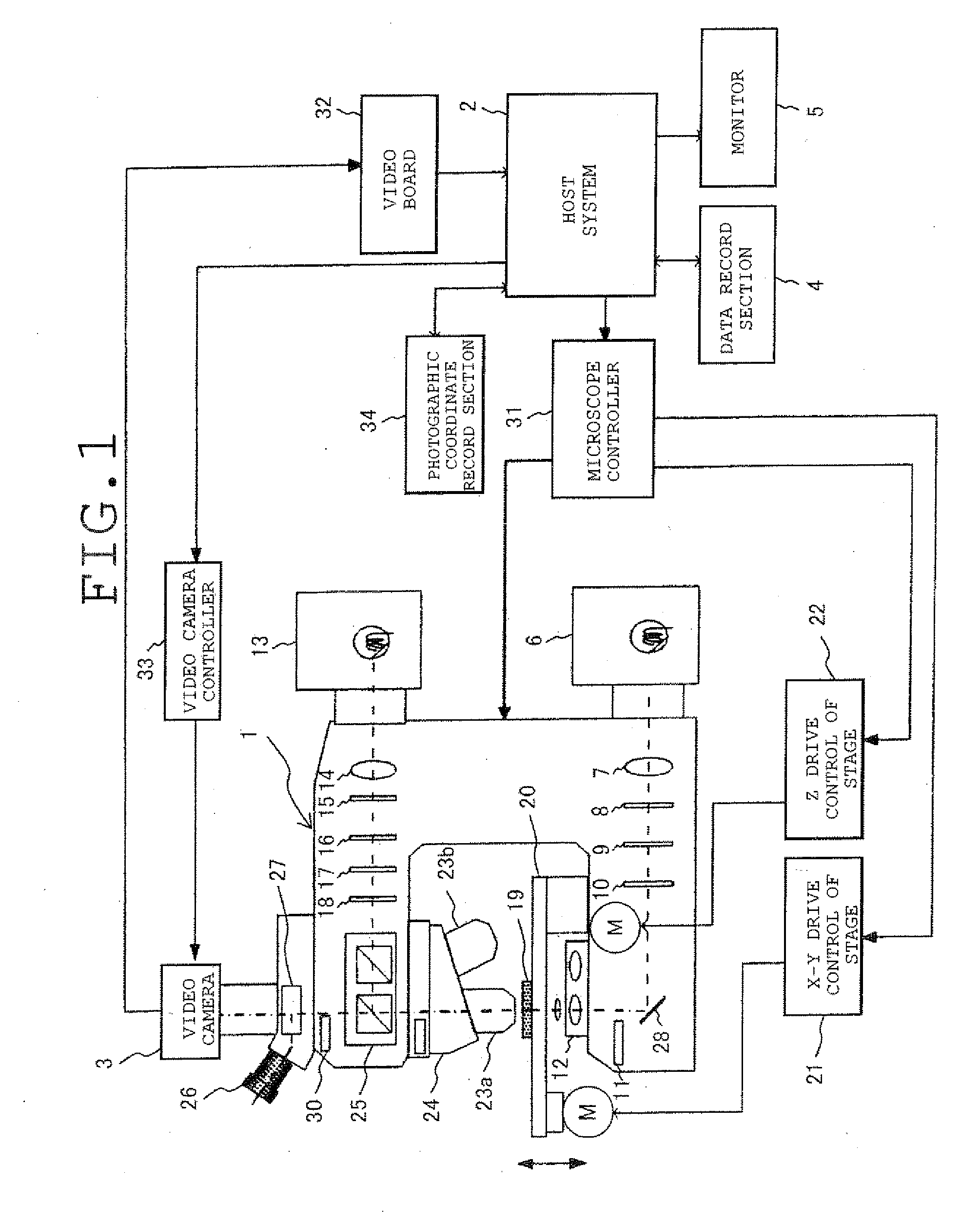
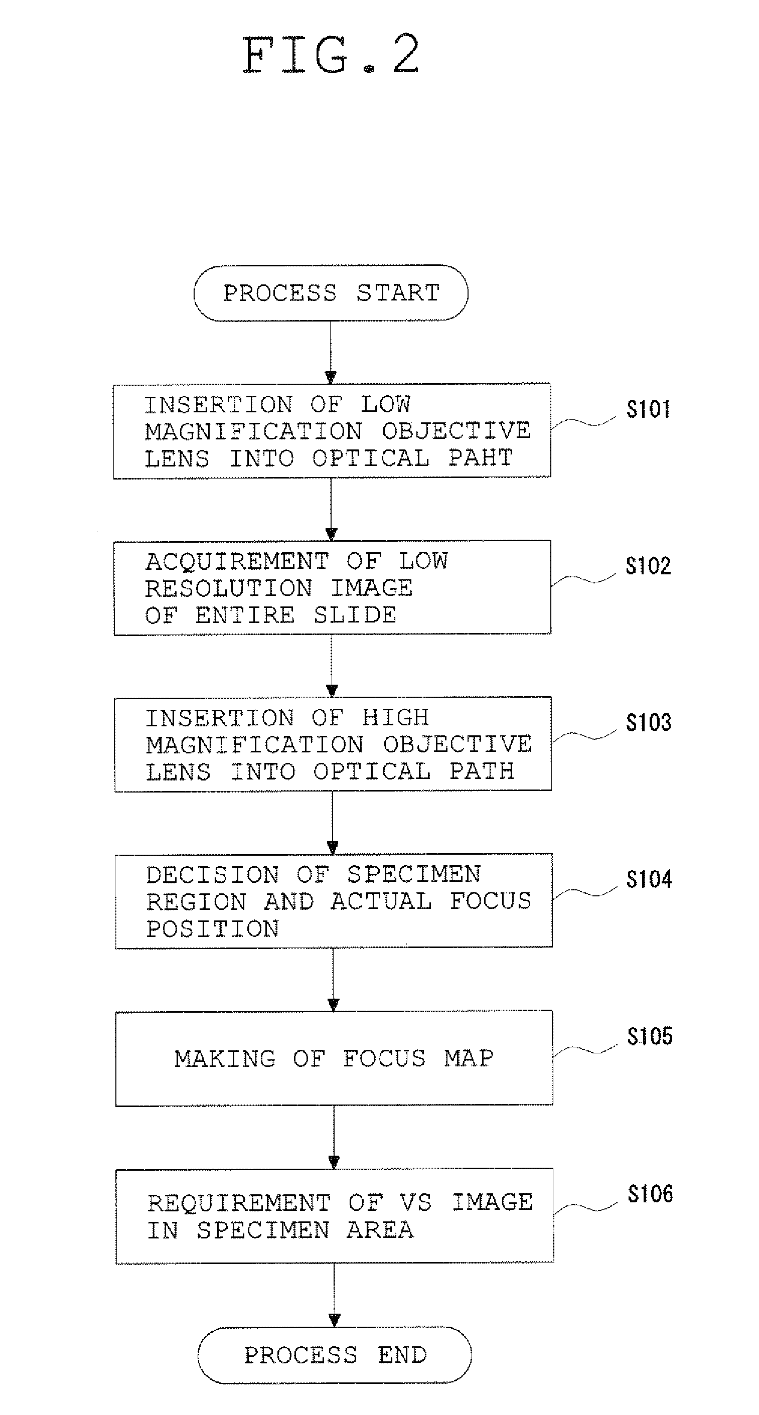
[0080]FIG. 2 is a flow chart showing the details of generation processing of the entire specimen VS image. FIG. 3 shows an example of a slide glass specimen (where the specimen 19 is placed on a slide glass 40). Also, although only the specimen 19 is shown in FIG. 1, the slide glass specimen is actually set on the motorized stage 20. FIG. 4 shows a state where the image of the entire specimen region is divided into a large number of small sections in order to produce a focus map. FIG. 5 shows an example of the data structure of the focus map.

[0081]In accordance with the flow chart of FIG. 2, the details of generation processing of the entire specimen VS image will be explained. First, in Step S101 of FIG. 2, in order to control the revolver 24 and confirm the presence of the specimen 19, a process that, for example, the objective lens 23 with 40× magnification is introduced into the optical path is executed. Next, in Step S102, a preset specimen...

embodiment 2

[0188]This embodiment treats the abnormality determination processing of Steps S185 and S186 in FIG. 11, in Embodiment 1, as a primary determination processing of normality / abnormality of the cell region 120. Following this abnormality determination processing, a secondary determination processing of normality / abnormality of the cell region 120 described below is performed and thereby an attempt is made to improve the determination accuracy of normality / abnormality of the cell region 120.

[0189]In the secondary determination processing, the objective lens 23 with higher magnification than that used in generating the entire specimen VS image is used, and a determination is three-dimensionally made as to whether the cell region 120 extracted by the process of Step S122 of FIG. 7 has an abnormal cell. In the following, the secondary determination processing is described with reference to FIGS. 16A-16D. FIG. 16A is a schematic view showing a state where cells overlap in the specimen 19. ...

embodiment 3

[0200]The present embodiment is designed to reduce photographing time and image capacity, etc. by stopping the photographing of sectioning image in a different focal position used a higher-magnification objective lens and the generation of the three-dimensional VS image, with respect to the cell able to determine whether it is normal or abnormal from the VS image of the entire specimen generated from the microscope images photographed by using a common objective lens. The present embodiment is described below by using FIGS. 17A to 17C and 18.

[0201]FIG. 17A is a view showing an example of an abnormality determination table of isolated and scattered cells in which the determination on the need for a detailed image is also possible. FIG. 17B is a view showing an example of an abnormality determination table of the cell mass in which the determination on the need for a detail image is also possible. The abnormality determination table shown in FIGS. 17A and 17B is designed so as to be a...


PUM


Abstract

A microscope system has a VS image generation means for generating a virtual slide image of a specimen which is constructed by mutually connecting a plurality of microscope images with a first photomagnification photographed and acquired whenever an objective lens and the specimen are relatively moved in a direction perpendicular to the optical axis and which represents the entire image of the specimen, an object-of-interest set means setting an object of interest with respect to the entire image of the specimen represented by the VS image, and a three-dimensional VS image generation means for generating a three-dimensional VS image which is constructed by connecting the microscope images at different focal positions in accordance with the same focal position and which is constructed from the microscope images with a second photomagnification higher than the first photomagnification and represents the image of the object of interest.

Description

[0001]This application claims benefits of Japanese Patent Application No. 2008-012651 filed in Japan on Jan. 23, 2008, the contents of which are incorporated herein by reference.BACKGROUND OF THE INVENTION[0002]1. Field of the Invention[0003]This invention relates to microscope technology and in particular, to the technology of a microscope system suitable for use in cytology in which a microscope is used to make the record and / or observation of a high-vision and high-definition microscope image.[0004]2. Description of Related Art[0005]In general, the cytologic diagnosis is made, for example, as follows. First, a cytotechnologist uses an objective lens with relative low (for example, 10×) magnification to perform the screening of the entire specimen and prosecutes the search of a malignant cell or an exceptional cell (such a cell is called an “abnormal cell” in the present invention). Here, when a suspectable cell has been found, the objective lens is replaced with that of high (for...

Claims


Application Information

Patent Timeline
IPC IPC(8): H04N7/18
CPCG01N21/6458G02B21/367G06T5/50G06T7/0012G06T2207/30024G06T2207/10016G06T2207/10056G06T2207/10148G06T2200/04G06V20/695
Inventor YAMADA, TATSUKI
Owner EVIDENT CORP
Why Eureka
Try Eureka