Outdoor luminaire using light emitting diodes

a technology of light-emitting diodes and outdoor luminaires, which is applied in outdoor lighting, lighting and heating apparatus, lighting heating/cooling arrangements, etc., can solve the problems of poor color rendition, endanger our environment, and color of light output, and achieve the effect of facilitating heat dissipation

Inactive Publication Date: 2009-08-27
MANES ROBERT JOEL
View PDF4 Cites 136 Cited by
  • Summary
  • Abstract
  • Description
  • Claims
  • Application Information

AI Technical Summary

Benefits of technology

[0020]In accordance with the present invention, there is provided a luminaire that uses Light Emitting Diodes as a light source, which is intended to be securely mounted outdoors on a pole or arm of widely varying diameter. The luminaire is modular, in the sense that a major component may be removed, repaired and / or replaced for maintenance or for upgrade purposes, without tools, and without modification to any other component in the luminaire. The luminaire's main component is a light engine comprised of Light Emitting Diodes mounted to a thermally conductive circuit board, which in turn is mounted to a thermally dissipative heat sink which resides on the outside of the luminaire. The thermally dissipative heat sink is specifically constructed to take full advantage of horizontal surface winds at the recommended mounting height of the luminaire, to aid in the dissipation of heat created by the Light Emitting Diodes and power components. The Light Engine is mounted in a housing facing downward, directly over an aperture, or hole in the lower housing, whereby one of several different lenses may be placed, depending upon the lighting requirements of the user. This structure and method of manufacture allows for use of almost any LED technology that exists, as well as those in the emergent and conceptual stages.

Problems solved by technology

In an effort to increase light output for energy expended, lighting methods are employed that seriously endanger our environment.
These dangers range from the color of the light output (poor color rendition), to excess light not well-controlled (dark-sky and trespass light pollution and security risks caused by poor visual acuity), to the chemicals included in the operational product, such as mercury, which is used in Low and High Pressure Sodium, Mercury Vapor and fluorescent technologies.
The use of LEDs is rising in these markets due to decreasing costs of manufacture, energy savings over other technologies and longevity, which results in lowered maintenance costs.
Even as we strive to increase efficiency, the fact remains that a majority of the power consumed in the modern light bulb is lost by way of heat generated.
Enter the white LED—whereby light is produced from a solid state device, is highly directional in nature, and has an incredibly long life span.
Several companies are attempting to develop street lighting technologies using LEDs retrofitted to existing lighting housings, such as “Cobra” head street lights and “Box” area lighting, but none have developed an economically viable street or area light centered on LEDs.
Developing LED “retrofit” products, that is, products that are meant for installation into existing housings presents certain problems.
High ambient temperatures and normal LED operating temperatures severely limit the number of LEDs that can be placed within such a housing, thereby reducing, or limiting, the amount of light produced by these inventions.
Without enough light output, the market narrows greatly as lighting requirements and published standards can not be met.
Unfortunately, CF lighting also contains mercury and although these products produce more light per watt consumed, they pose an environmental hazard and require proper handling and disposal methods.
Several LED-base street lights have emerged, but these units do not take into account proper light distribution. particularly to meet National and International lighting standards.
In addition, these units display poor thermal management, as well as laborious maintenance routines to replace or repair the units.

Method used


Image

  • Outdoor luminaire using light emitting diodes
  • Outdoor luminaire using light emitting diodes
  • Outdoor luminaire using light emitting diodes

Examples


Embodiment Construction

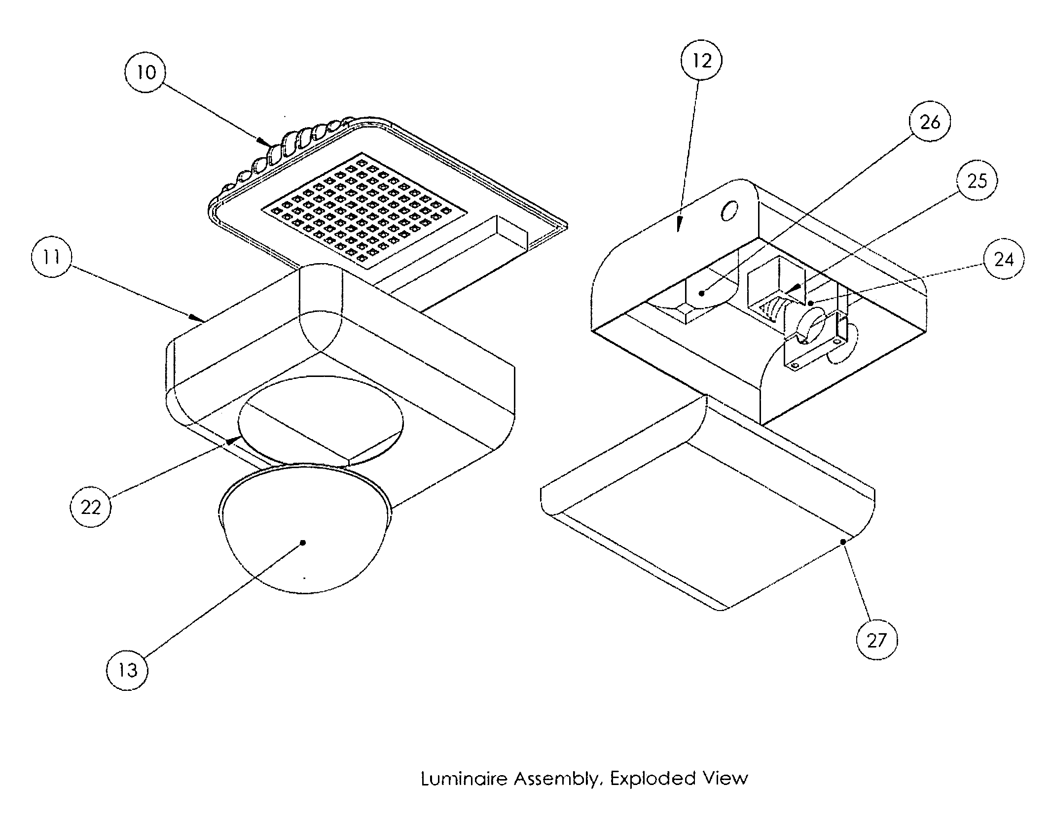
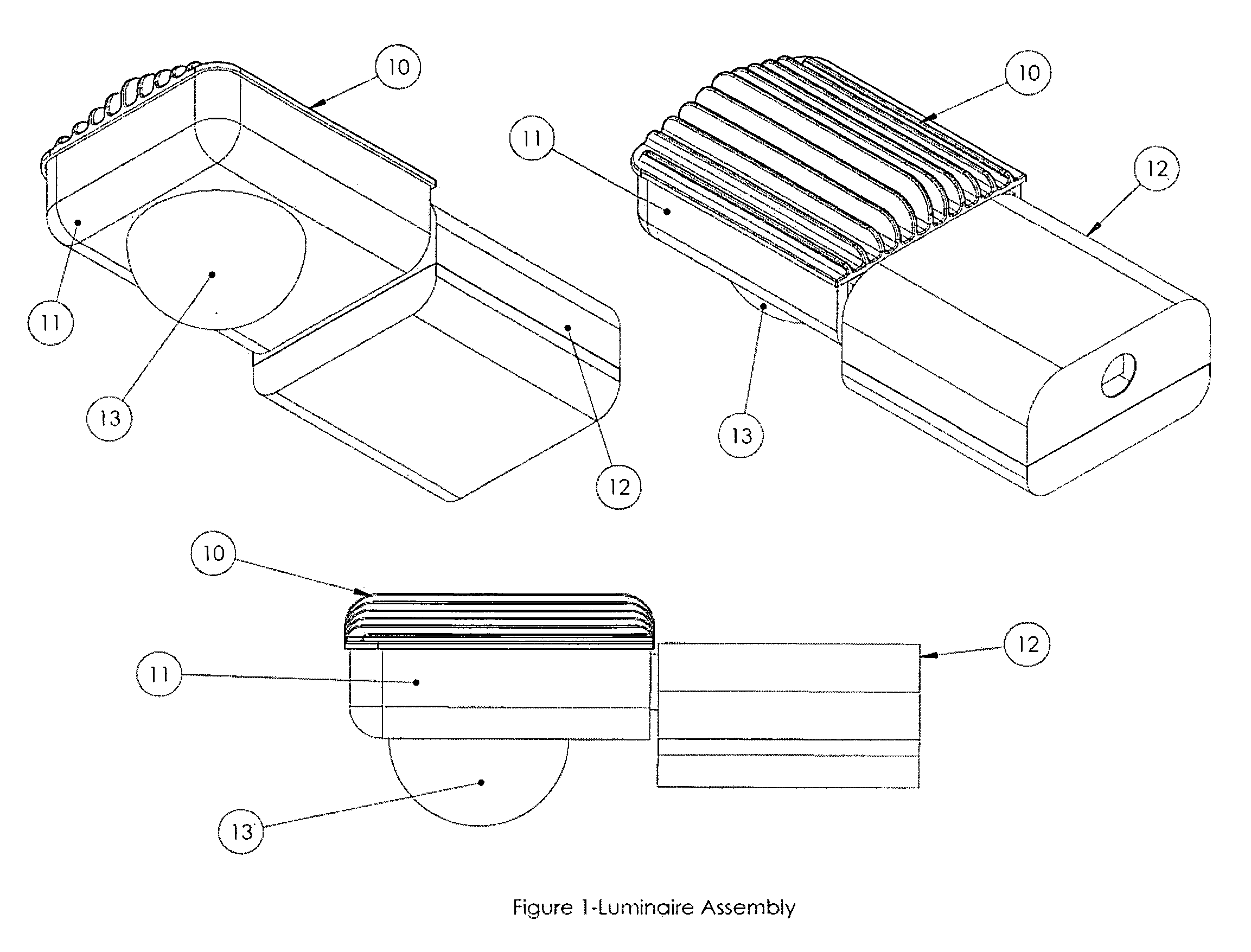
[0028]FIG. 1 is a perspective view of the luminaire assembly. This shows the external components of the luminaire in its assembled form. A rear housing 12 is mounted to a main housing 11 via standard hardware, soldering or welding method, as desired. These housings may be made of any material strong enough to support the weight of the components as well as any local, state, or federal regulations or any other recommendations for such a product. A heat sink 10 is placed on top of the main housing 11 and secondary optics 13 are installed below the heat sink 10.

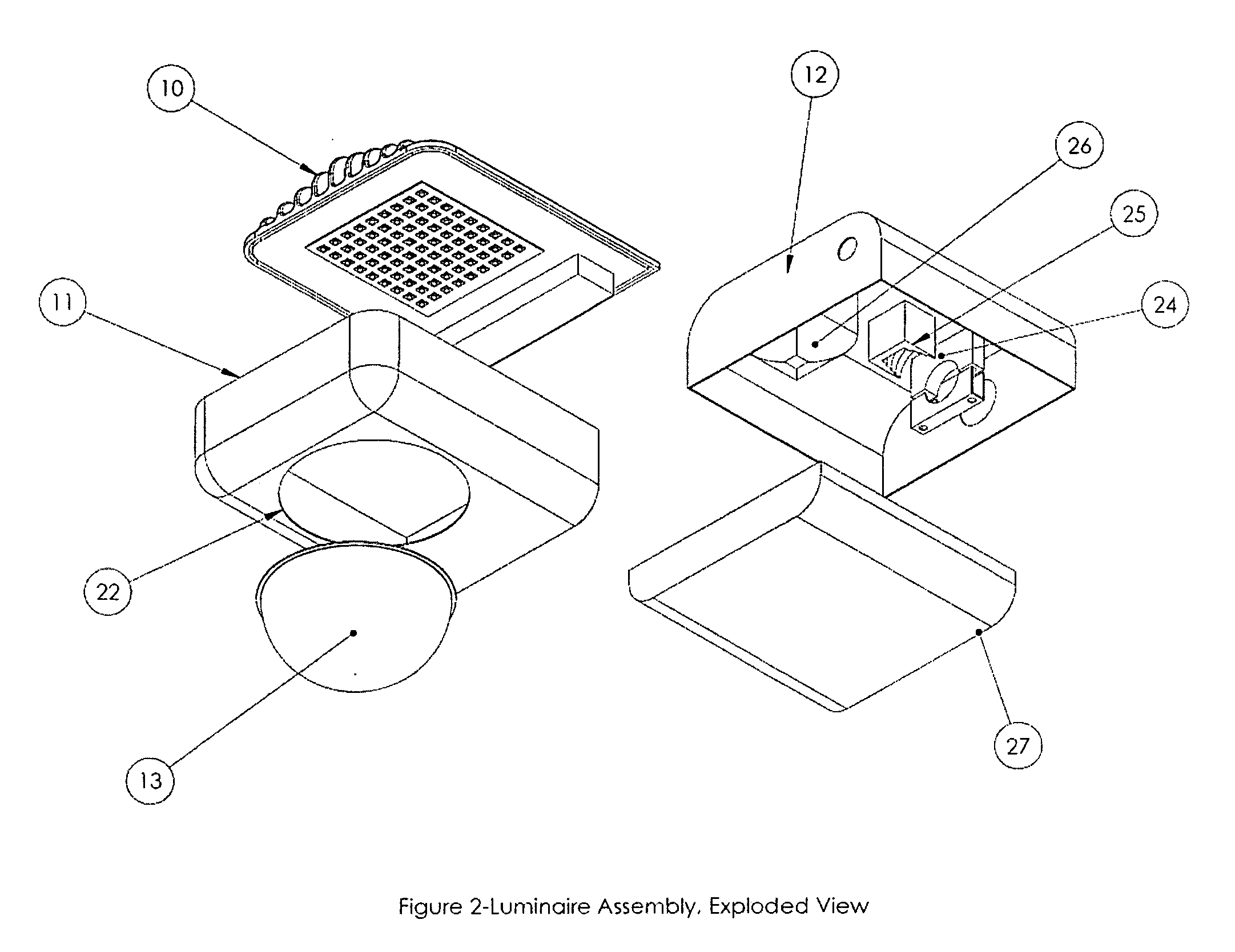
[0029]FIG. 2 is an exploded view of the luminaire assembly. The luminaire is mounted on a pole or arm through a hole in the rear housing 12. Depending upon the diameter of the pole or arm, it is placed as far into the front arm mount 25 as the steps will allow, providing a secure fit for a pole or arm of greatly varying diameter. The rear arm mount 24 is then clamped over the pole and secured by means of bolts, screws or tool-le...


PUM


Abstract

A luminaire that uses Light Emitting Diodes as a light source, and which is intended to be securely mounted outdoors on a pole or arm of widely varying diameter. The luminaire is modular, in the sense that a major component may be removed, repaired and/or replaced for maintenance or for upgrade purposes, without tools, and without modification to any other component in the luminaire. The luminaire's main component is a light engine comprised of Light Emitting Diodes mounted to a thermally conductive circuit board, which in turn is mounted to a thermally dissipative heat sink which resides on the outside of the luminaire. The thermally dissipative heat sink is specifically constructed to take full advantage of horizontal surface winds at the recommended mounting height of the luminaire, to aid in the dissipation of heat created by the Light Emitting Diodes and power components. The Light Engine is mounted in a housing facing downward, with respect to light output, directly over an aperture, or hole in the lower housing, whereby one of several different lenses may be placed to provide a desired photometric output. This structure and method of manufacture allows for use of almost any LED technology that exists, as well as those in the emergent and conceptual stages.

Description

FIELD OF THE INVENTION[0001]The present invention relates to general street and area lighting and, more particularly, general lighting luminaires using Light Emitting Diodes.BACKGROUND OF THE INVENTION[0002]According to the US Department of Energy, current available technologies in the field of lighting may account for up to 19% of the world's energy consumption. In an effort to increase light output for energy expended, lighting methods are employed that seriously endanger our environment. These dangers range from the color of the light output (poor color rendition), to excess light not well-controlled (dark-sky and trespass light pollution and security risks caused by poor visual acuity), to the chemicals included in the operational product, such as mercury, which is used in Low and High Pressure Sodium, Mercury Vapor and fluorescent technologies.[0003]The Light Emitting Diode (LED) has long been used for decorative purposes and as indicators, in everyday applications such as traf...

Claims


Application Information

Patent Timeline
Patent Type & Authority Applications(United States)
IPC IPC(8): F21V1/00F21V21/00F21V29/00
CPCF21S8/086F21S48/328F21V29/004F21V29/85F21Y2101/02F21V29/75F21V29/763F21W2131/103F21Y2105/16F21Y2115/10
Inventor MANES, ROBERT JOEL
Owner MANES ROBERT JOEL
Why Eureka
Try Eureka