
Image forming apparatus, image forming method, and image forming program product

a technology of image forming and apparatus, applied in the direction of instruments, visual presentation using printers, electrographic processes, etc., can solve the problems of inflexible addressing such a relationship, conventional technology is not capable of thickening vertical lines, conventional technology only addresses vertical lines, etc., and achieves the effect of simple configuration

Inactive Publication Date: 2009-08-27
RICOH KK
View PDF7 Cites 17 Cited by
  • Summary
  • Abstract
  • Description
  • Claims
  • Application Information

AI Technical Summary

Benefits of technology

[0015]The present invention provides an image forming apparatus, an image forming method, and an image forming program product, in which one or more of the above-described disadvantages are eliminated.
[0016]A preferred embodiment of the present invention provides an image forming apparatus, an image forming method, and an image forming program product capable of processing pixels of vertical lines and diagonal lines expressed by input multi-value pixel data, with a simple configuration and in an appropriate manner.
[0020]According to one embodiment of the present invention, pixels in vertical lines and diagonal lines in the input multi-value pixel data can be processed with a simple configuration and in an appropriate manner.

Problems solved by technology

The above problem does not only arise when forming a monochrome image using black toner, but also when forming a color image using color toner.
The above conventional technology is not capable of thickening the vertical lines to solve the problem where the lines become thinner than those of the original image.
However, the conventional technology is not capable of flexibly addressing such a relationship.
Moreover, the conventional technology only addresses vertical lines, and does not address diagonal lines.
For this reason, if the technology were applied to image data with a larger number of bits, the hardware configuration would be extremely extensive.
Accordingly, such a configuration would be complex and expensive.

Method used


Image

  • Image forming apparatus, image forming method, and image forming program product
  • Image forming apparatus, image forming method, and image forming program product
  • Image forming apparatus, image forming method, and image forming program product

Examples


first embodiment

Functions of First Embodiment

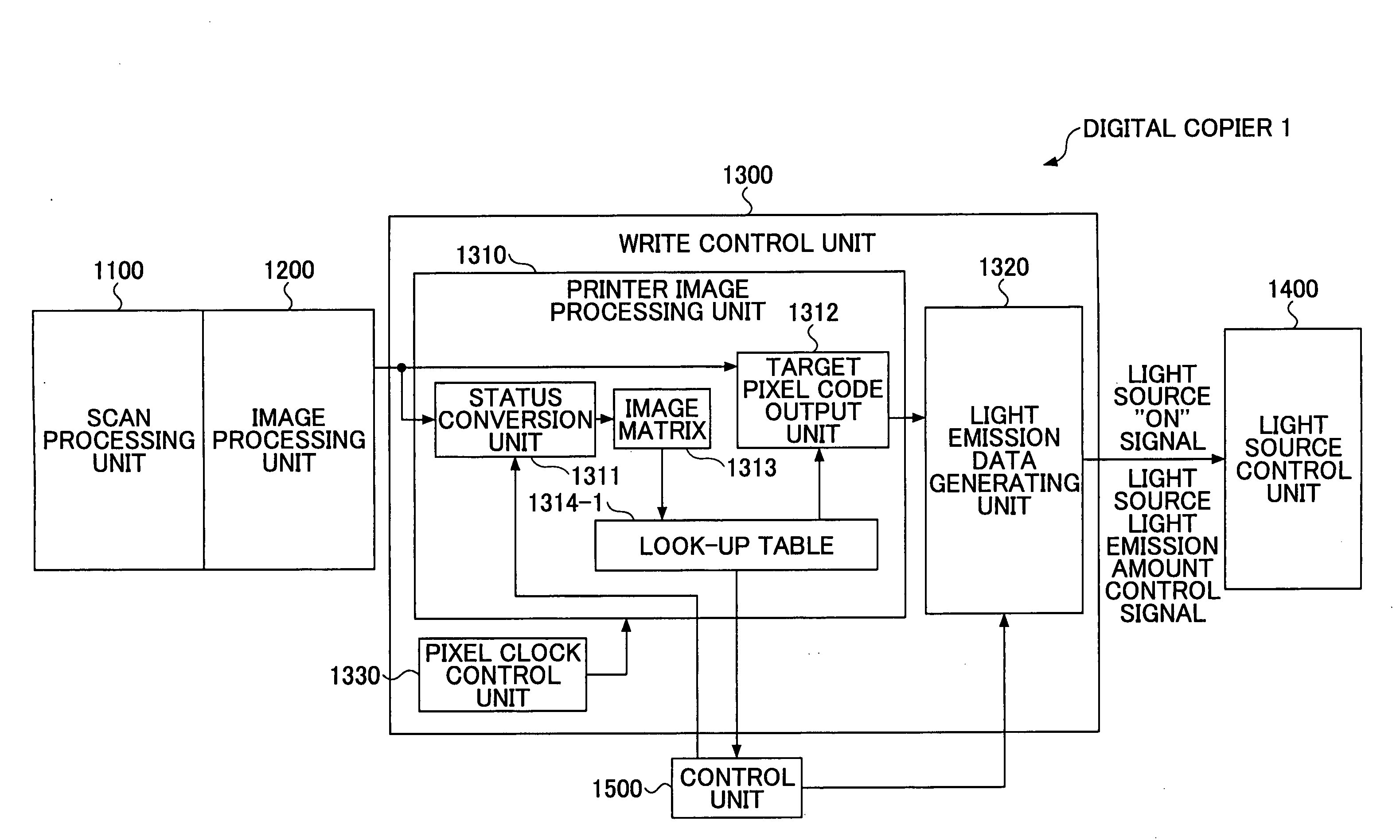
[0121]A description is given of a function of the first embodiment. The digital copier 1 according to the first embodiment performs an image forming process of appropriately determining the vertical lines and adjusting the thicknesses according to settings.

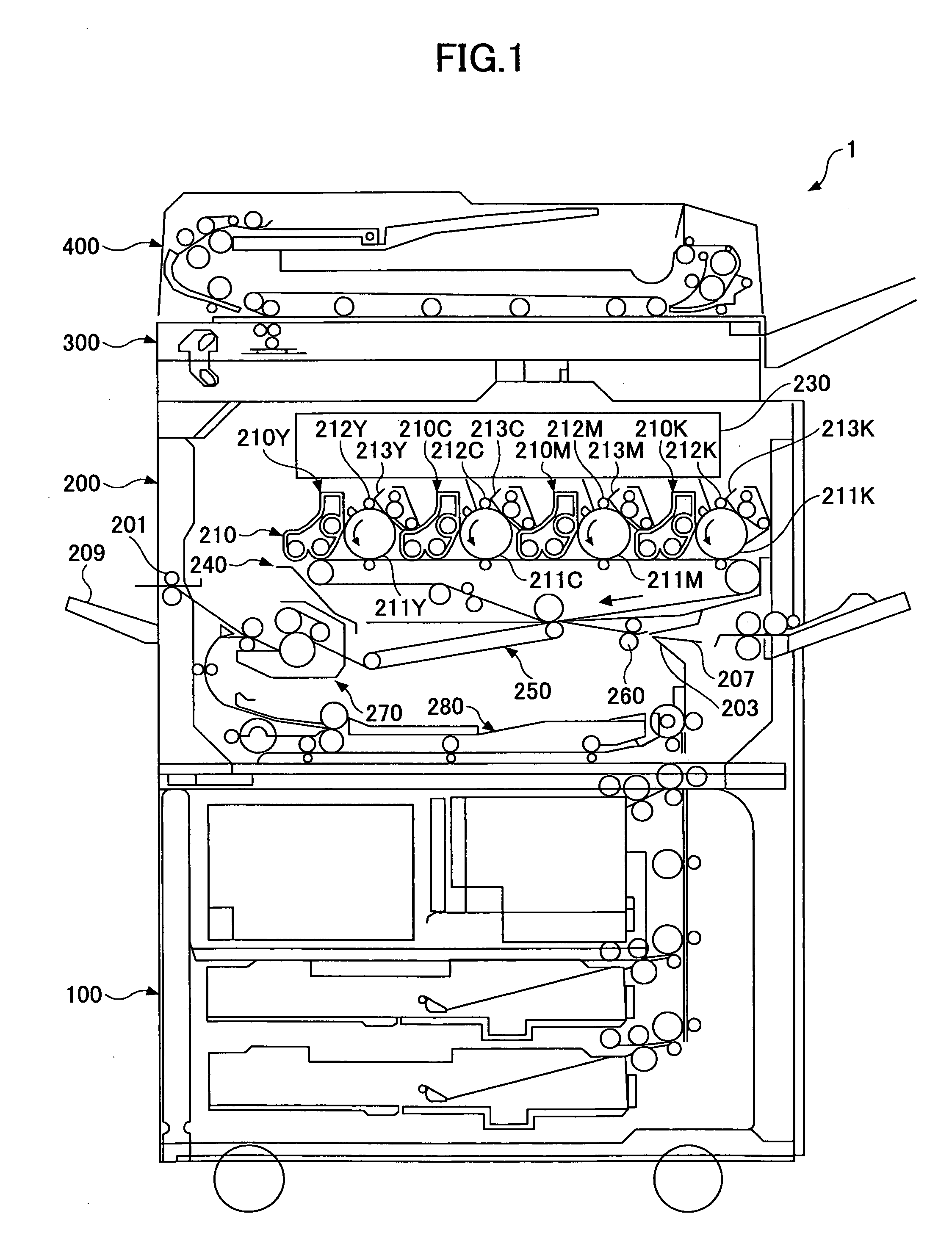
[0122]The digital copier 1 inputs the analog image data that has undergone photoelectric conversion of the CCD of the scanner section 300, into the scan processing unit 1100. The scan processing unit 1100 performs processes such as a sampling process, an A / D conversion process, and a shading correction process, and outputs the image data to the image processing unit 1200.

[0123]The image processing unit 1200 of the scanner section 300 performs image quality correction processes on the image data, such as a zooming process, a rotating process, and an edge process. Then, the image processing unit 1200 converts the image data into multi-value pixel data (for example, of 4 bits / 16 values), and outputs the m...

second embodiment

Functions of Second Embodiment

[0198]A description is given of a function of the second embodiment. The digital copier 2 according to the second embodiment performs an image forming process of appropriately evaluating vertical lines, horizontal lines, and diagonal lines, and appropriately adjusting the widths of lines according to settings.

[0199]The digital copier 2 has a characteristic that even if the same input multi-value pixel data was input, the vertical lines and the horizontal lines formed on transfer sheets would have different thicknesses, spaces would be formed between dots in a diagonal line such that the diagonal line becomes light (thin), and the lines would become thin or thick according to the resolution, which may lead to degraded image quality.

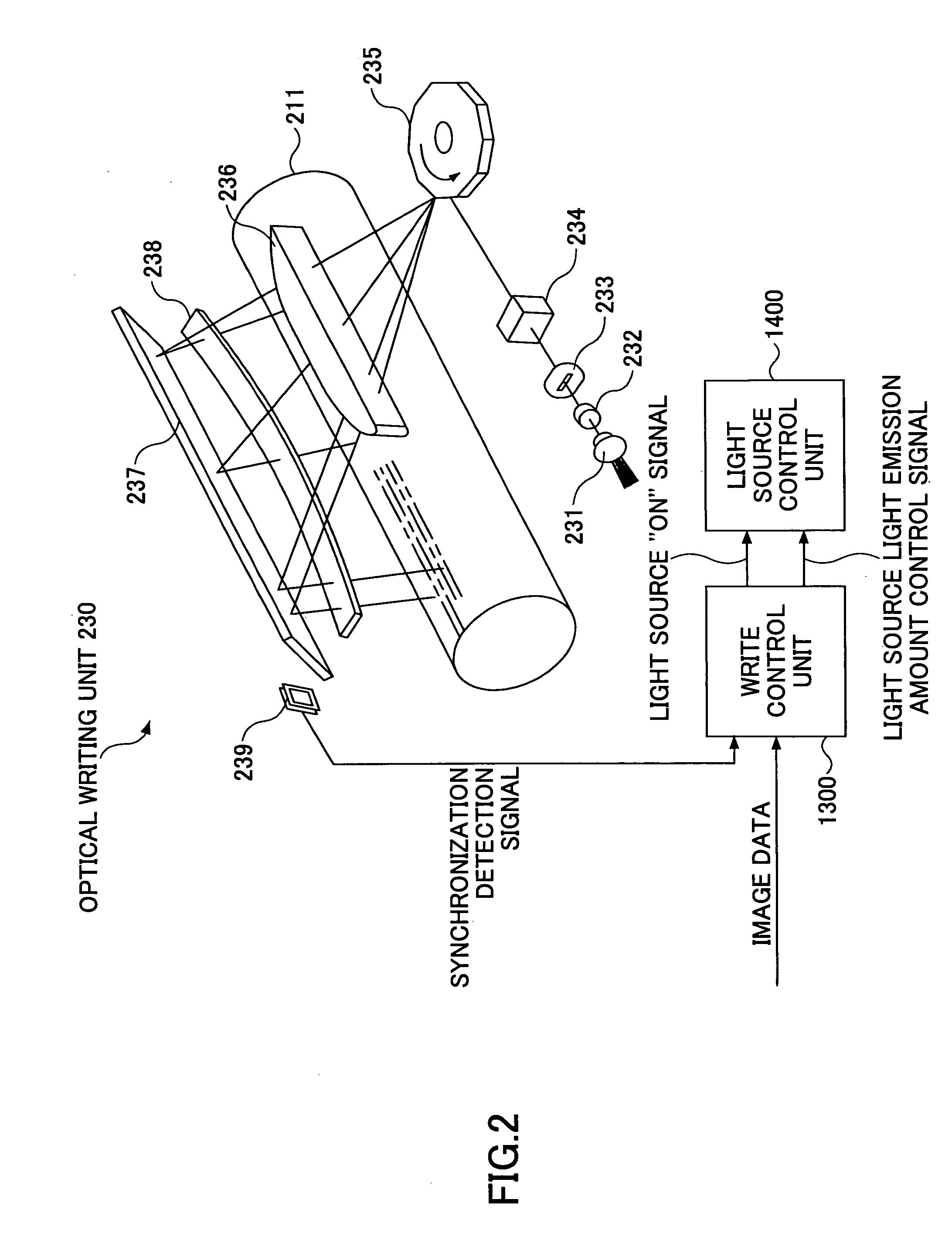
[0200]For example, when a line is formed by lighting the LD array 231 for a period of time corresponding to a line of one pixel in the main scanning direction, a light beam is radiated by lighting the LD array 231 for a period...

third embodiment

[0277]Next, a description is given of a third embodiment of the present invention. FIG. 22 is a block diagram of a relevant circuit of a digital copier 3 according to the third embodiment. In the second embodiment, the printer image processing unit 1310 stores edge information in the edge information storage 1315, and performs a process of changing, in accordance with the edge information in the edge information storage 1315, the reference LUT to be referred to in the look-up table 1314-2 which is determined based on the edge information and the status values in the image matrix 1313.

[0278]However, as shown in FIG. 22, an edge information matrix 1316 can be provided in the digital copier 3 according to the third embodiment.

[0279]FIG. 23 is an operation diagram of the image matrix 1313, the edge information storage 1315, and the edge information matrix 1316 shown in FIG. 22. As shown in FIG. 23, the edge information matrix (edge information storing unit) 1316 receives edge informatio...


PUM


Abstract

An image forming apparatus includes an image forming unit for forming an image; a status conversion unit for converting the multi-value pixel data into status values; plural reference look-up tables each indicating an association between an arrangement of the status values of a target pixel and adjacent pixels in a pixel window and an output data value of the multi-value pixel data to be output; a determining unit for determining a target reference look-up table based on the arrangement; and a generating unit configured to change an input data value of the multi-value pixel data, into the output data value of the determined target reference look-up table, and for outputting the multi-value pixel data to the image forming unit.

Description

BACKGROUND OF THE INVENTION[0001]1. Field of the Invention[0002]The present invention relates to an image forming apparatus, an image forming method, and an image forming program product.[0003]2. Description of the Related Art[0004]In an electrophotographic image forming apparatus such as a laser printer, a digital copier, a fax machine, and a multifunction peripheral, an image creating unit typically performs a negative / positive (N / P) process by radiating a light beam to a position where toner is to be applied in correspondence with an input image (hereinafter, “toner application part”) to form an electrostatic latent image, and applying toner to the electrostatic latent image to develop the image. The volume of the applied toner varies depending on the diameter of the beam spot formed as the light beam reaches a scanning target surface, and also depending on developing conditions. Therefore, even if the same image data was input, the output images would vary.[0005]For example, whe...

Claims


Application Information

Patent Timeline
Patent Type & Authority Applications(United States)
IPC IPC(8): G03G15/043G06K15/02
CPCH04N1/40037
Inventor TANAKA, SHINYAFUJIMOTO, HIDEOMINAMBA, MUTSUMIHAGIWARA, ATSUSHITAKANO, SATOSHINAGANO, HIROYUKI
Owner RICOH KK
Learn More