Fixing Device and Image Forming Apparatus

a technology of fixing device and image forming apparatus, which is applied in the direction of electrographic process apparatus, instruments, optics, etc., can solve the problems of large electronic power loss at the switching device, large ripple and flicker, and may produce an unfavorable influence on the power supply, so as to achieve a large electronic power loss

Inactive Publication Date: 2009-08-27
KYOCERA DOCUMENT SOLUTIONS INC
View PDF4 Cites 15 Cited by
  • Summary
  • Abstract
  • Description
  • Claims
  • Application Information

AI Technical Summary

Benefits of technology

[0011]However, the aforementioned technique may not perform the zero cross switching when the switching device is turned on, and may cause a large electronic power loss at the switching device. In addition, a restart of switching o

Problems solved by technology

However, the aforementioned technique may not perform the zero cross switching when the switching device is turned on, and may cause a large electronic power loss at the switching device.
In addition, a restart of switching oper

Method used


Image

  • Fixing Device and Image  Forming Apparatus
  • Fixing Device and Image  Forming Apparatus
  • Fixing Device and Image  Forming Apparatus

Examples


embodiment 1

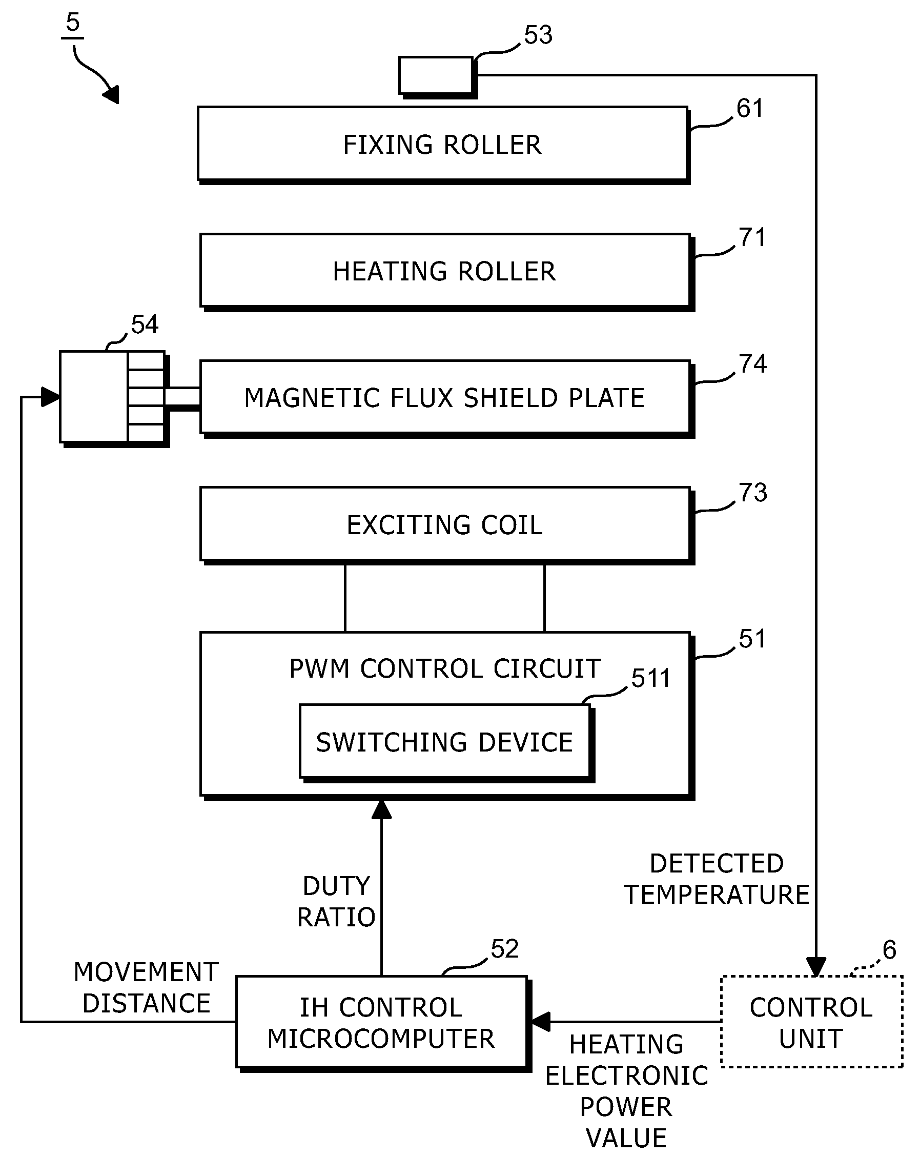
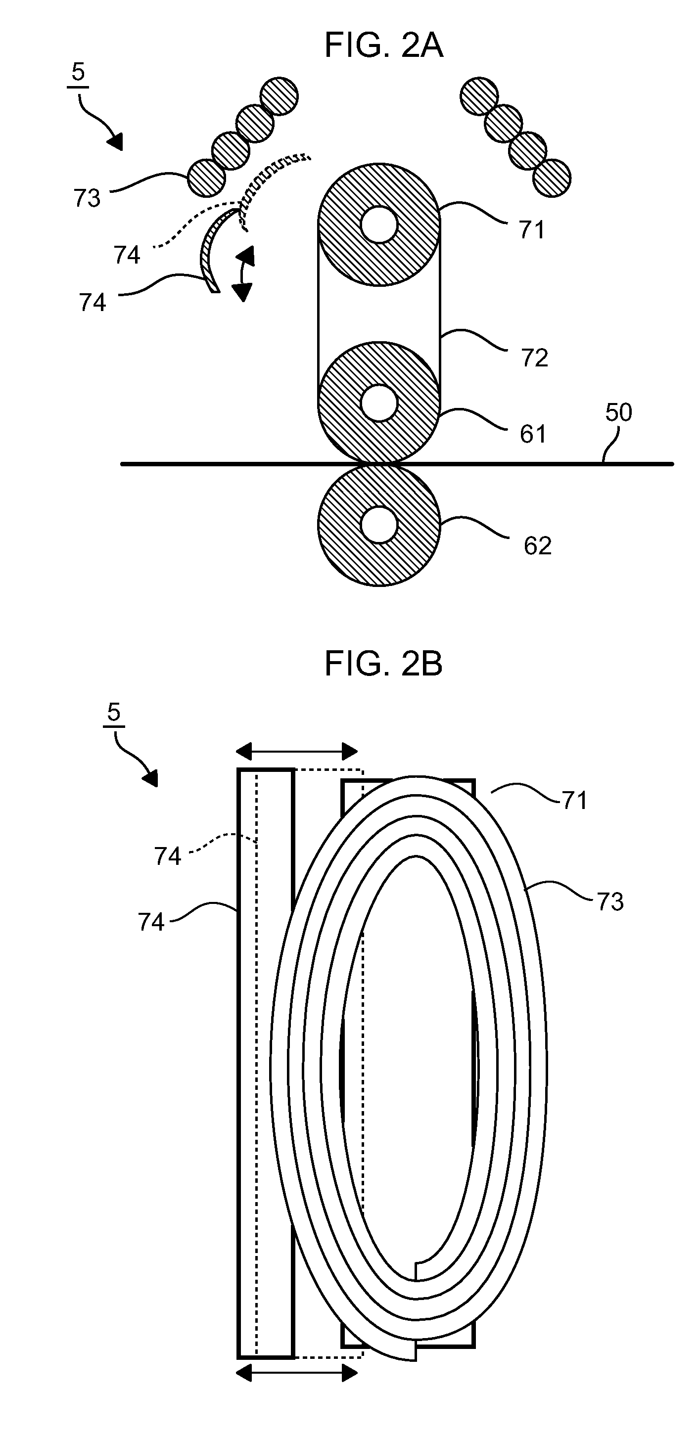
[0060]FIG. 1 shows a block diagram that indicates a schematic configuration of a copy machine according to Embodiment 1 of this invention. FIGS. 2A and 2B show diagrams that indicate a schematic configuration of a fixing device according to Embodiment 1 of this invention. FIG. 3 shows a block diagram that indicates a system configuration of the fixing device according to Embodiment 1 of this invention. FIG. 4 shows a flowchart that indicates an instance of procedures for a heating control process performed by the fixing device in the copy machine according to Embodiment 1 of this invention.

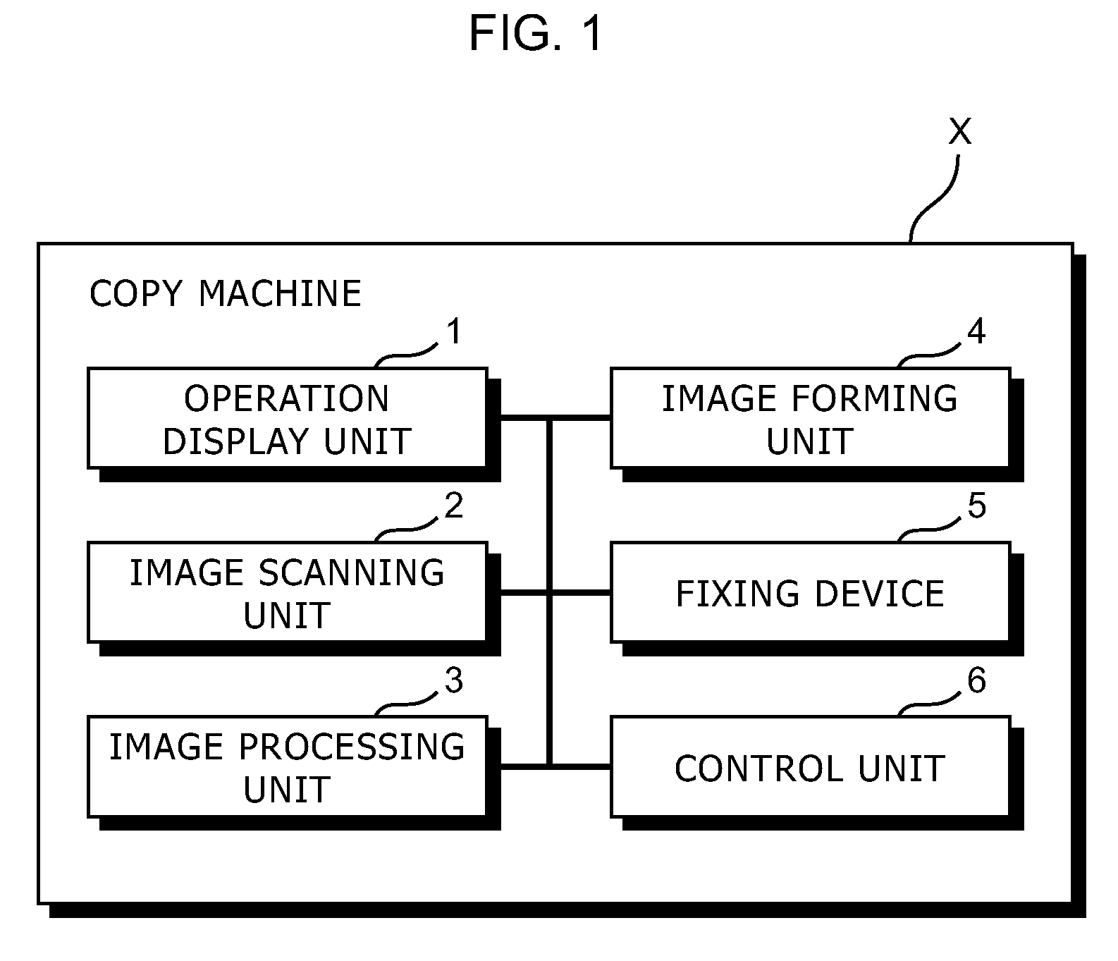
[0061]A copy machine X in Embodiment 1 is an instance of the image forming apparatus according to this invention, and this invention is also applied to a printer machine, a facsimile machine, a multi function peripheral, or the like.

[0062]With referencing to FIG. 1, a schematic configuration of the copy machine X according to Embodiment 1 of this invention is explained as follows. As shown in FIG....

embodiment 2

[0096]FIGS. 5A and 5B show diagrams that indicate a schematic configuration of a fixing device according to Embodiment 2 of this invention. FIG. 6 shows a block diagram that indicates a system configuration of the fixing device according to Embodiment 2 of this invention. FIG. 7 shows a flowchart that indicates an instance of procedures for a heating control process performed by the fixing device in the copy machine according to Embodiment 2 of this invention. FIG. 8 shows another instance of the fixing device according to Embodiment 2 of this invention.

[0097]A copy machine X in Embodiment 2 is an instance of the image forming apparatus according to this invention, and this invention is also applied to a printer machine, a facsimile machine, a multi function peripheral, or the like.

[0098]A schematic configuration of the copy machine X in Embodiment 2 is identical to that in Embodiment 1, and therefore it is not explained here.

[0099]The copy machine X of Embodiment 2 has a main featu...

embodiment 3

[0132]In Embodiment 2, the magnetic core 174 is moved, but in Embodiment 3, the fixing device has a configuration to move the exciting coil 173. This configuration is explained here.

[0133]In Embodiment 3, the fixing device 5 moves the exciting coil 173 away from the magnetic core 174 and / or the heating roller 171 to change strength of electromagnetic coupling between the exciting coil 173 and the magnetic core 174, and / or strength of electromagnetic coupling between the exciting coil 173 and the heating roller 171 in order to control an amount of a magnetic flux conducted from the exciting coil 173 to the heating roller 171.

[0134]For example, the driving mechanism supports the exciting coil 173 instead of the magnetic core 174; and in a heating control process performed by the IH control microcomputer 152, if the heating electronic power value is set as equal to or less than the minimum electronic power value, then the IH control microcomputer 152 keeps duty ratio of a switching ope...


PUM


Abstract

A fixing device has: (a) an electromagnetic coil placed with a gap from a member of a magnetic material to be heated; a switching device that supplies electronic power to the electromagnetic coil; (b) a switching control unit that controls duty ratio for the switching device under a condition that a load voltage and a load current of the switching device are substantially zero when the switching device is turned on and/or off; (c) a shield member capable of being placed between the electromagnetic coil and the member to be heated to shield the member to be heated against a magnetic flux from the electromagnetic coil; and (d) a shield control unit that controls a shield amount of the shield member by moving either the shield member or both the electromagnetic coil and the member to be heated.

Description

CROSS-REFERENCE TO RELATED APPLICATIONS[0001]This application relates to and claims priority rights from Japanese Patent Applications:[0002]No. 2008-044677, filed on Feb. 26th, 2008, and[0003]No. 2008-044687, filed on Feb. 26th, 2008, the entire disclosures of which are hereby incorporated by reference herein.BACKGROUND OF THE INVENTION [0004]1. Field of the Invention[0005]This invention relates to a fixing device that heats a fixing roller by electromagnetic induction heating, and an image forming apparatus that has the fixing device.[0006]2. Description of the Related Art[0007]An image forming apparatus such as printer machine, copy machine, facsimile machine or multi function peripheral has a fixing device that heats a hollow fixing roller of a magnetic material by magnetic induction heating. Specifically, an electromagnetic coil is placed with a gap from the fixing roller. Conducting an AC current through the electromagnetic coil generates a magnetic flux through the fixing roll...

Claims


Application Information

Patent Timeline
IPC IPC(8): G03G15/20
CPCG03G2215/2032G03G15/2053
Inventor YODA, JUNYAKADOBAYASHI, IZUMI
Owner KYOCERA DOCUMENT SOLUTIONS INC
Why Eureka
Try Eureka