
Method and Device for Controlling a Computer System Having At Least Two Execution Units and One Comparator Unit

a computer system and control method technology, applied in the field of methods and devices for controlling a computer system, can solve the problems of maintaining the restriction of the processor system operation, and achieve the effect of increasing the robustness of errors and increasing the (partial) availability of system functions

Inactive Publication Date: 2009-08-27
ROBERT BOSCH GMBH
View PDF14 Cites 38 Cited by
  • Summary
  • Abstract
  • Description
  • Claims
  • Application Information

AI Technical Summary

Benefits of technology

[0008]An objective of the present invention is a method for operating a dual-core processor (or a dual-processor system) with the aim of an increased robustness with regard to errors and an increased (partial) availability of the system function when transient and permanent errors occur in the processor system. In an advantageous exemplary embodiment, this may be achieved while maintaining the original execution time for the individual program segments.
[0010]The advantages of the present invention include alternating assignment of the master function to the at least two execution units and thus the alternating use of the core results of a dual-core or multi-core computer that is operated in the lockstep mode. Thus, when certain boundary conditions are taken into account, a restricted operation of the processor system may be maintained even after a discrepancy in the redundantly calculated results has been detected. This is advantageous particularly in real-time applications in which a shutdown of the system due to processor errors is not desired in every operating state.
[0011]In an exemplary embodiment, an additional advantage results from the fact that an error in the execution units of the processor system is able to be located, that the faulty execution unit is deactivated, and that the system having the non-faulty execution unit continues to operate until a system state is reached that is not critical for shutdown or a previously specified maximum operating time in this mode is exceeded.

Problems solved by technology

Thus, when certain boundary conditions are taken into account, a restricted operation of the processor system may be maintained even after a discrepancy in the redundantly calculated results has been detected.

Method used


Image

  • Method and Device for Controlling a Computer System Having At Least Two Execution Units and One Comparator Unit
  • Method and Device for Controlling a Computer System Having At Least Two Execution Units and One Comparator Unit
  • Method and Device for Controlling a Computer System Having At Least Two Execution Units and One Comparator Unit

Examples


Embodiment Construction

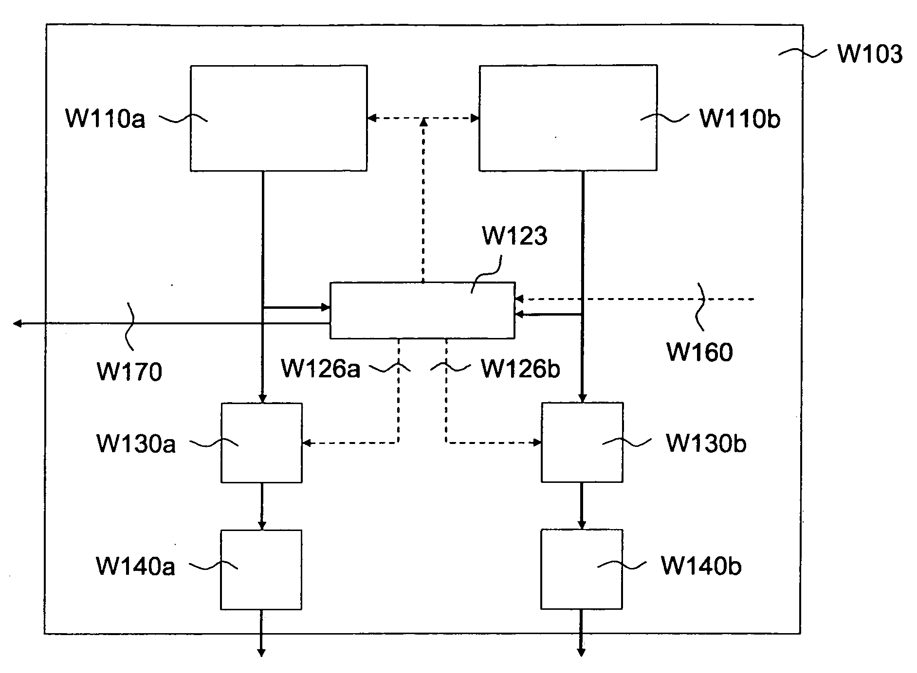
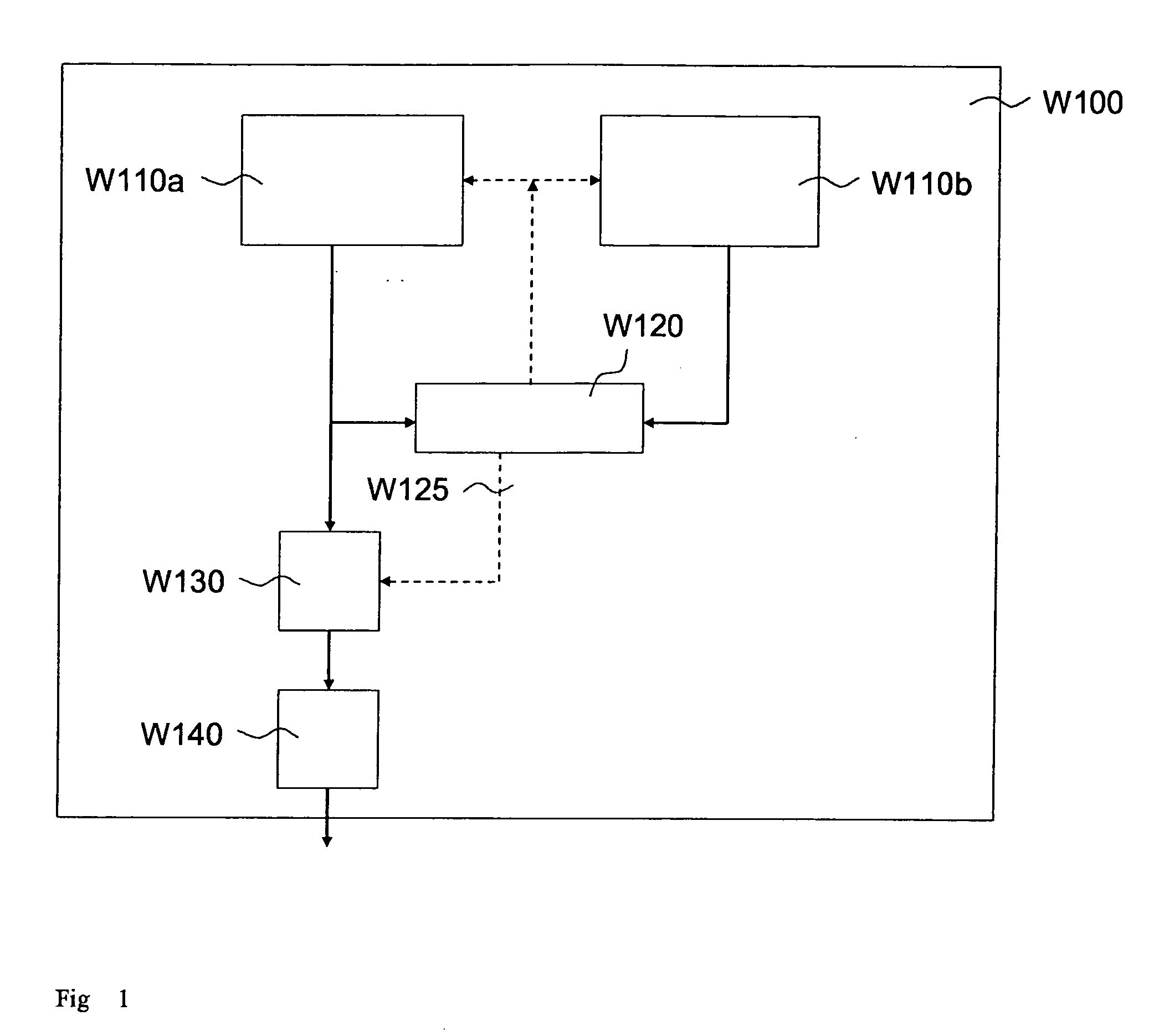
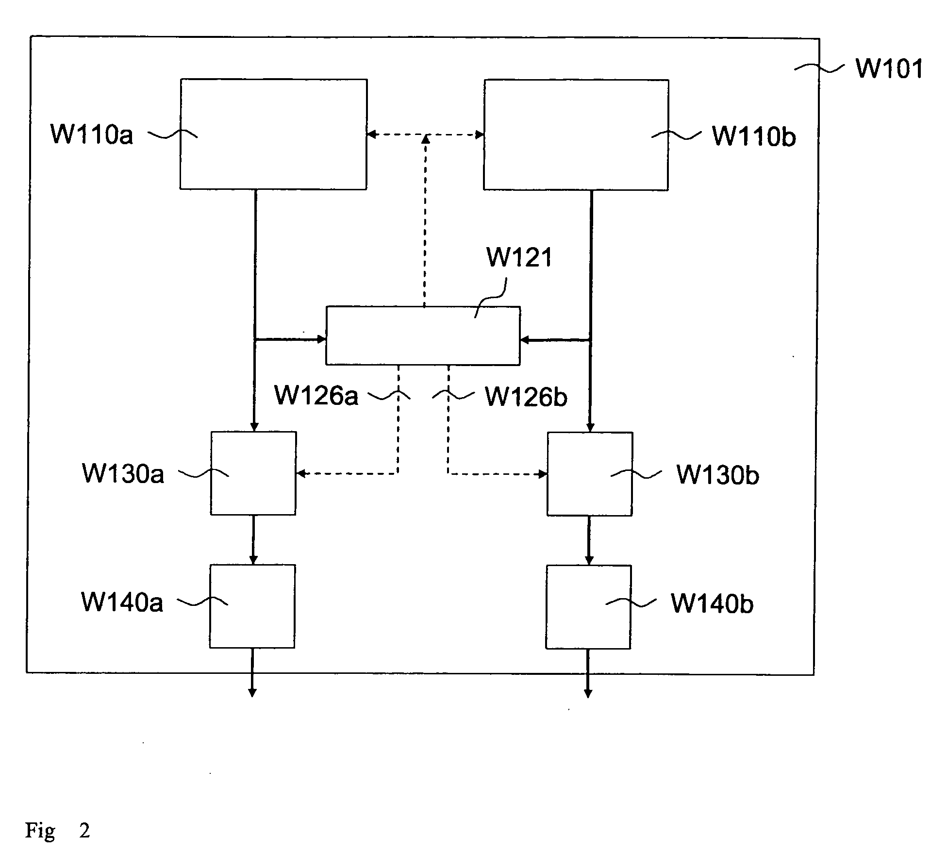
[0022]FIG. 1 shows a processor system W100 having multiple execution units W110a, W110b, for example, a dual-core computer and a comparator unit W120 that may be implemented in hardware. This processor system is operated in the lockstep mode. In this operating mode, the results of the execution units are compared, which may be after each clock cycle. In this context, an execution unit may be implemented both as a processor / core / CPU and as an FPU (floating point unit), DSP (digital signal processor), co-processor, or ALU (arithmetic logical unit), in each case having any number of assigned register records. In this context, exactly one execution unit is connected via an interruption or enabling unit W130 to a system interface W140 or directly to the data / address bus of the processor system. This execution unit is the only one to generate results that are further processed in the processor system. Therefore, the execution unit connected to system interface W130 or to the data / address ...


PUM


Abstract

A method for controlling a computer system having at least two execution units and one comparator unit, which system is operated in the lock-step mode and in which the results of the at least two execution units are compared, wherein when or after an error is detected by the comparator unit, an error-detection mechanism is processed on at least one execution unit for this execution unit.

Description

FIELD OF THE INVENTION[0001]The present invention relates to a device and a method for maintaining a system function in the event of errors in a processor system having two cores as well as a corresponding processor system.BACKGROUND INFORMATION[0002]Redundancies, for example, of microcontrollers (μC), but also of components of a μC, such as, for example, the CPU (central processing unit), for the purpose of error detection are known from the related art. In this context, redundantly calculated data and redundantly generated signals are compared for consistency by a comparator unit.[0003]A microcontroller having redundant CPUs is also called a dual-core microcontroller (dual-core μC). In a dual-core μC, both CPUs are able to operate synchronously, that is, in parallel (in lockstep mode) or in a manner that is time-delayed by a few clock cycles. Both CPUs receive the same input data and process the same program or the same instructions. If an error exists in one of the redundantly im...

Claims


Application Information

Patent Timeline
IPC IPC(8): G06F11/07
CPCG06F11/1641G06F11/1654G06F11/165
Inventor WEIBERLE, REINHARDMUELLER, BERNDGMEHLICH, RAINER
Owner ROBERT BOSCH GMBH
Learn More