Remote Setting for Electronic Systems in a Projectile for Chambered Ammunition

a technology of electronic system and remote setting, which is applied in the direction of combustion process, combustion ignition, lighting and heating apparatus, etc., can solve the problems of reducing flexibility, limiting the types of targets that a tank can effectively engage, and lack of flexibility, so as to achieve more economical installation

Active Publication Date: 2009-09-03
GENERAL DYNAMICS ORDNANCE & TACTICAL SYST CANADA VALLEYFIELD INC
View PDF11 Cites 26 Cited by
  • Summary
  • Abstract
  • Description
  • Claims
  • Application Information

AI Technical Summary

Benefits of technology

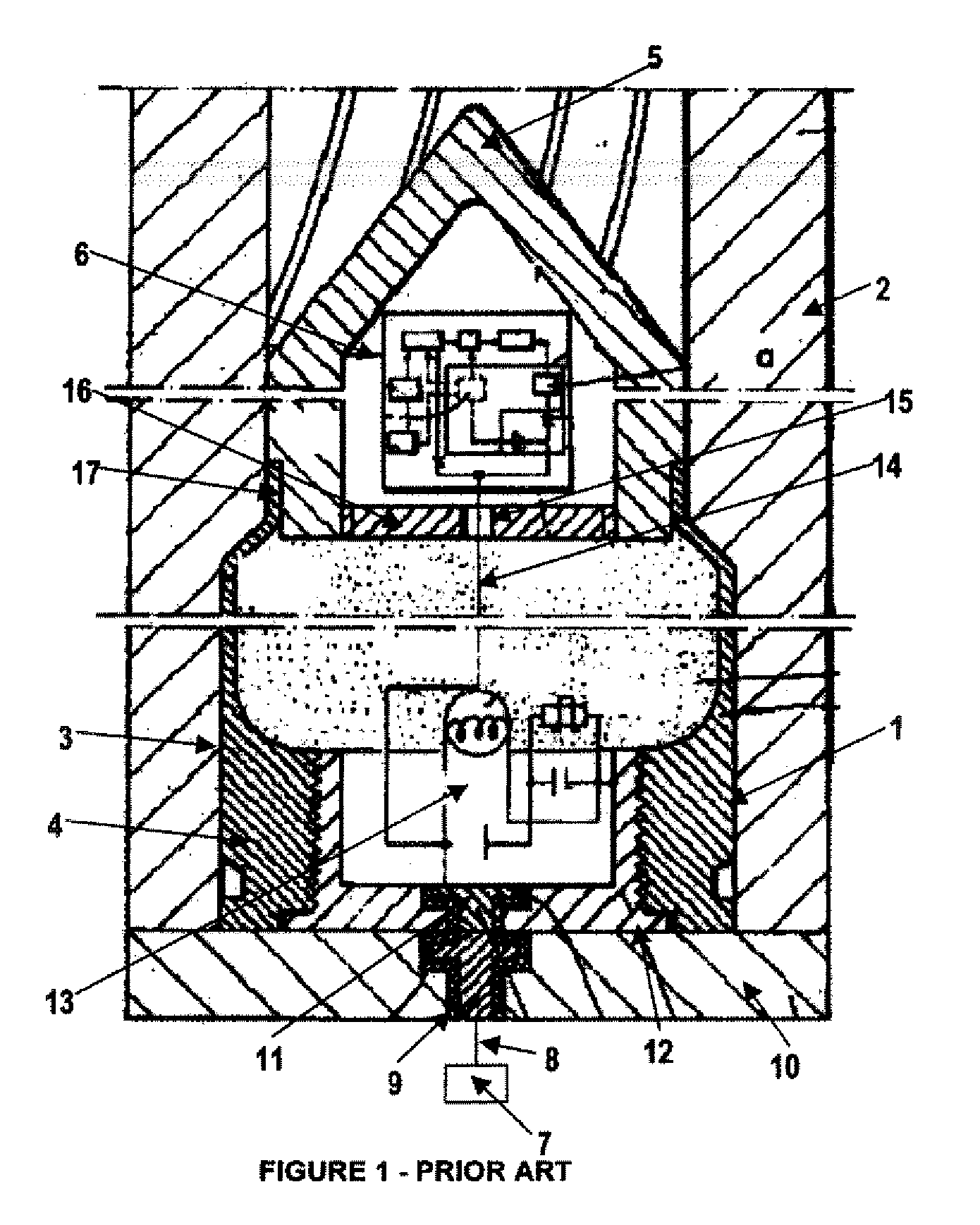
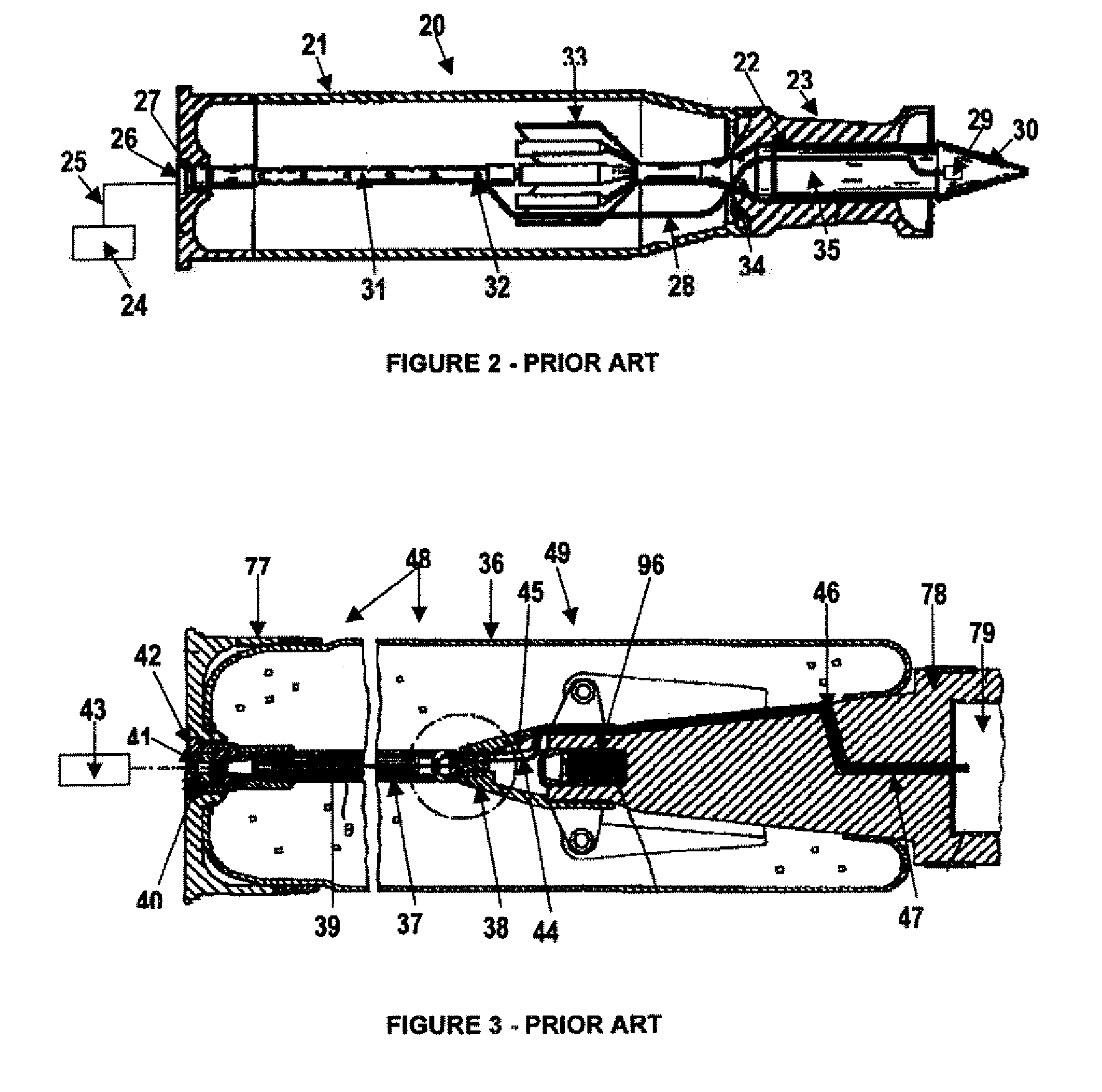
[0022]The invention features an electromechanical circuit that transmits electrical setting signals from the fire control system of, for example, a tank in one application, to a programmable fuze situated in the high explosive projectile of a fully-chambered cartridge in a medium or large-calibre gun. One aspect of the invention is to provide a reliable electromechanical circuit for the transmission of the setting signal that is both easier, from a production point of view, and more economical to install in contrast to the transmitting circuits described by the prior art.

Problems solved by technology

The separate formats of this current technology reduce flexibility and severely limit the types of targets that a tank can effectively engage rapidly.
This lack of flexibility also makes tanks vulnerable to attack from, for example, an infantryman armed with a shoulder-fired rocket-propelled grenade (RPG) launcher, if they are loaded with APFSDS cartridges.
This is not possible with the limited choice of discrete ammunition now available for tanks carrying 105 mm guns.
Without an air burst capability at its disposal, defense against such an attack is compromised, nor can effective offensive action be taken against “soft” targets such as helicopters, light aircraft or lightly protected personnel.
However, the existence of large numbers of 105 mm tank guns in the inventories of many armies makes it impractical to require burdensome modifications to all of them for new, hard wired circuitry.
This patent, however, which has now expired, does not give details as to how the various circuits are physically located inside the cartridge.

Method used


Image

  • Remote Setting for Electronic Systems in a Projectile for Chambered Ammunition
  • Remote Setting for Electronic Systems in a Projectile for Chambered Ammunition
  • Remote Setting for Electronic Systems in a Projectile for Chambered Ammunition

Examples


Embodiment Construction

[0052]In FIG. 4 large calibre cartridge 50 comprises: cartridge case 51 with cartridge case base 52; head assembly contact 67; head assembly holder 53; primer flash tube 54; propellant 55; driving band 56; projectile 57 comprising projectile body 57A, projectile base 58, projectile nose 59 and a load exemplified by high explosive 60 fill; tracer unit 61A with electrically-conductive tracer container 61 containing tracer compound 62; and programmable multi-functional electronic fuze (or fuze) 63 containing fuze electronic circuit 76 as an example of programmable electronics. Fire control system 64 is hardwired to firing pin 65, which is located in the breech (not shown), by conductor 66. Firing pin 65 bears directly on electrode 80 (see FIG. 6A) of head assembly contact 67. Through intermediaries, insulated electrode 80 is eventually connected to conductor 68, which then runs along the outside of primer flash tube 54 to connect with rear tracer contact 69.

[0053]The rear tracer contac...


PUM


Abstract

A fuze setting circuit in an artillery or tank shell having a case with a press-fitted head assembly is provided with an electromechanical fuze-wiring link that is completed electrically by mechanical assembly of a tracer-carrying projectile on the shell casing, and by the rotational attachment of a programmable fuze onto the projectile.

Description

FIELD OF THE INVENTION[0001]This invention relates to the field of medium and large-calibre tank and artillery ammunition and provisions for a capability of remotely programming such ammunition in one of several predefined modes immediately prior to firing. In particular, it relates to the electromechanical configuration of the circuitry required when incorporating a multi-functional electronic fuze or other type of trigger mechanism into the projectile of a multipurpose, large-calibre high-explosive or other pay-load carrying cartridgeBACKGROUND OF THE INVENTION[0002]It is now customary to provide circuitry that allows the fire control system of a gun to remotely select the fuze operating mode as, for example, either point detonation, or point detonation delay, or air burst through the use of a timing or turn-counter device, or proximity operating modes, or any combination thereof, after the ammunition is loaded into the gun and before it is fired.[0003]Although the invention descr...

Claims


Application Information

Patent Timeline
Patent Type & Authority Applications(United States)
IPC IPC(8): F42C19/00
CPCF42C19/06F42C11/002
Inventor DIETRICH, STEPHANGELINAS, ROGER
Owner GENERAL DYNAMICS ORDNANCE & TACTICAL SYST CANADA VALLEYFIELD INC
Why Eureka
Try Eureka