Rotor sail and ship with a rotor sail

a technology of rotor sails and sails, applied in the field of rotor sails, can solve the problems of environmental pollution caused by the drive, and achieve the effect of reducing the risk of damage to the environmen

Inactive Publication Date: 2009-09-03
MAGNUS ROTOR SOLAR SYST
View PDF10 Cites 31 Cited by
  • Summary
  • Abstract
  • Description
  • Claims
  • Application Information

AI Technical Summary

Benefits of technology

[0004]The object of the invention is therefore to develop the rotor sail in such a way that it can be operated in a more environmentally friendly manner.

Problems solved by technology

The environmental pollution caused by the drive is, however, a disadvantage.

Method used


Image

  • Rotor sail and ship with a rotor sail
  • Rotor sail and ship with a rotor sail

Examples


Embodiment Construction

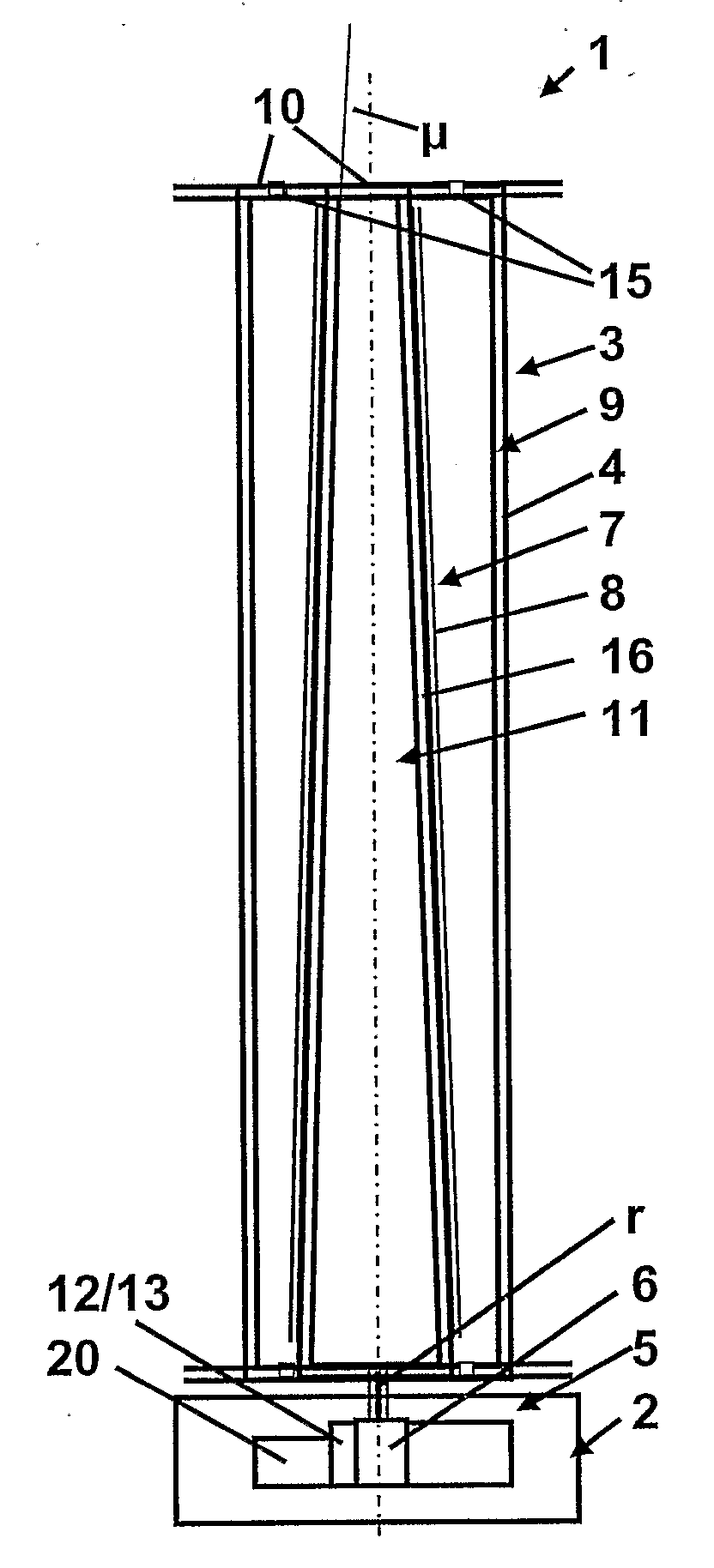
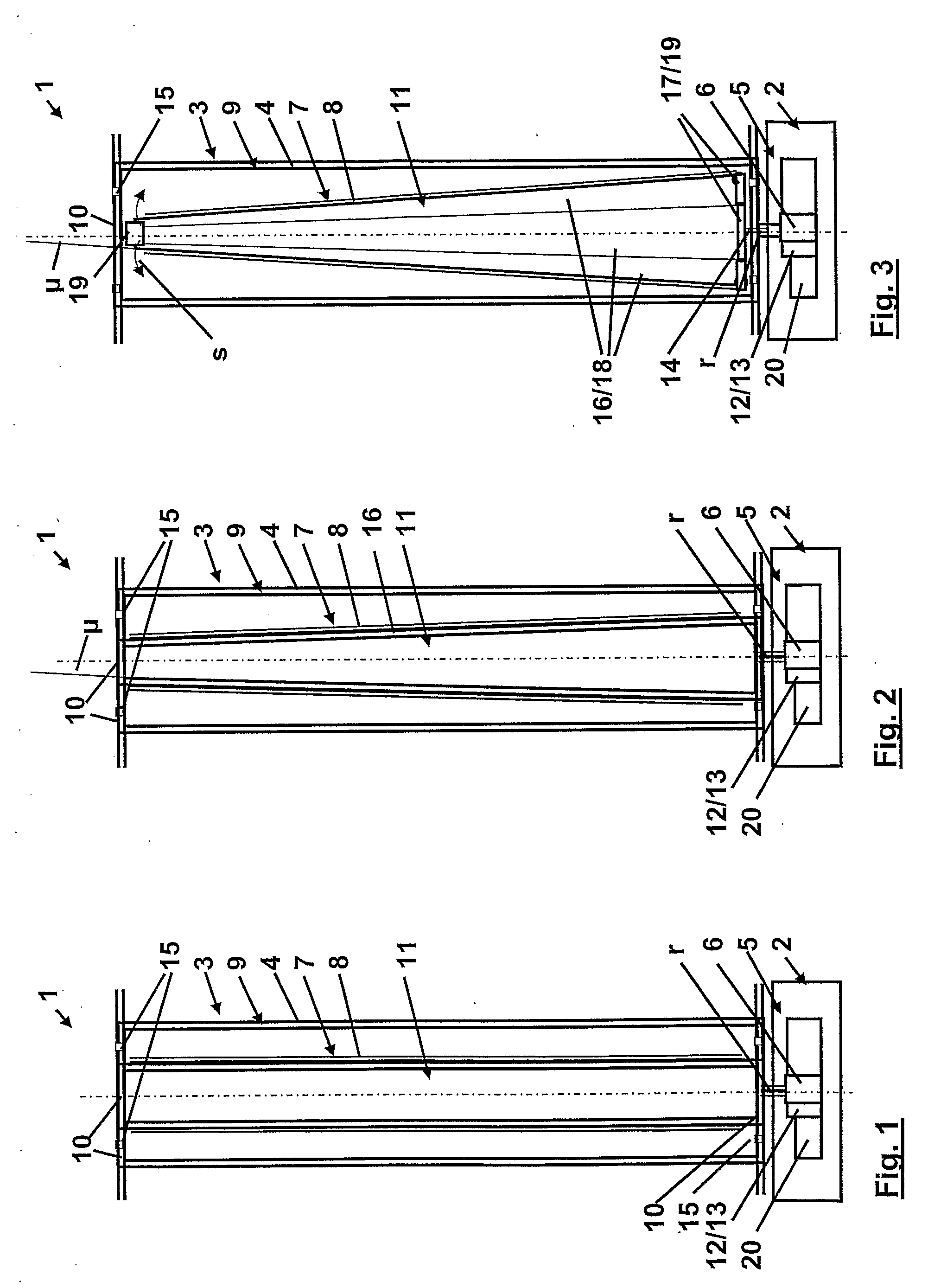
[0029]FIGS. 1 to 3 each show, in the form of a highly schematic and simplified diagram, a rotor sail 1 in three different embodiments. Rotor sail 1 has a base 2, a rotary cylinder 3, which is mounted on base 2 in a manner permitting rotation about its longitudinal axis designed as the rotor axis r, and whose enclosing outer surface 4 serves as a wind-exposed surface in operation, and a drive 5 having an electric motor 6 for rotating rotary cylinder 3. Drive 5 and motor 6 are located in base 2, where rotor axis r extends into drive 5.

[0030]According to embodiments of the invention, a photovoltaic system 7 with solar cells 8 is provided to generate electric energy for drive 5. Solar cells 8 are arranged in rotary cylinder 3 in such a way that their photoelectrically active layers face toward enclosing outer surface 4. Provision is furthermore made for rotary cylinder 3 to be of transparent design in its sleeve 9 and in its end face 10 pointing away from base 2. Moreover, end faces 10 ...


PUM


Abstract

A rotor sail is provided having a base (2) and a rotary cylinder (3) mounted on the base (2) in a manner permitting rotation about its longitudinal axis designed as the rotor axis (r), and a drive (5) for rotating the rotary cylinder (3). An enclosing outer surface (4) of the rotary cylinder serves as a wind-exposed surface in operation. So that the rotor sail can be operated in a more environmentally friendly manner, it is provided with a photovoltaic system (7) having solar cells (8) to generate electric energy for the drive (5) having an electric motor (6). The solar cells (8) are located in the rotary cylinder (3) and have photoelectrically active layers facing toward the enclosing outer surface (4). The rotary cylinder (3) has a sleeve (9) which is transparent, at least in an area covering the solar cells (8).

Description

CROSS-REFERENCE TO RELATED APPLICATIONS[0001]This application is a Section 371 of International Application No. PCT / DE2006 / 001821, filed Oct. 17, 2006, which was published in the German language on Apr. 26, 2007, under International Publication No. WO 2007 / 045220 A1 and the disclosure of which is incorporated herein by reference.BACKGROUND OF THE INVENTION[0002]The invention relates to a rotor sail with a base, a rotary cylinder, which is mounted on the base in a manner permitting rotation about its longitudinal axis designed as the rotor axis, and whose enclosing outer surface serves as a wind-exposed surface in operation, and a drive for rotating the rotary cylinder.[0003]A rotor sail of this kind is also known as a Flettner rotor, which rotates when driven by a drive. When the wind flows against the rotating rotor sail, a force transverse to the direction of flow of the wind is formed in accordance with the so-called Magnus effect as a result of surface friction between the rotor...

Claims


Application Information

Patent Timeline
Patent Type & Authority Applications(United States)
IPC IPC(8): B63H9/02B63J99/00
CPCY02T70/58B63H9/02Y02T70/5236
Inventor KIND, ROLF
Owner MAGNUS ROTOR SOLAR SYST
Why Eureka
Try Eureka