
Powder coating components to reduce friction, increase wear resistance, and improve cleanability

a technology of powder coating and friction reduction, applied in the field of tribological arts, can solve the problems of difficult removal, degrading the desirable corrosion-resistant surface, and affecting the appearance of black oxide, so as to improve wear resistance, reduce surface friction, and enhance the effect of wear resistan

Active Publication Date: 2009-09-03
SPAN TECH
View PDF28 Cites 22 Cited by
  • Summary
  • Abstract
  • Description
  • Claims
  • Application Information

AI Technical Summary

Benefits of technology

[0009]In accordance with a first aspect of the invention, a conveyor component is provided for use in a conveying system for supporting or conveying product with improved wear resistance, enhanced cleanability, and reduced surface friction. The component comprises an electrically conductive substrate having a surface coated with a shell comprising a generally clear or translucent powder coating formed of a polymer selected from the group consisting of a polyamide, polyolefin, polyester, urethane, epoxy, acrylic, and mixtures thereof. As a result, the shell is essentially invisible to the naked eye.
[0016]Still a further aspect of the invention is a method of improving wear resistance, enhancing cleanability, and reducing surface friction in a conveyor system. The method comprises the steps of powder coating a steel component of the conveyor system using a polymer selected from the group consisting of a polyamide, polyolefin, polyester, urethane, epoxy, acrylic, and mixtures thereof. The method further comprises the step of using the powder coated steel component to hold or convey product.
[0018]Still a further aspect of the invention is a method of conveying product by way of a stationary wear surface in a more efficient manner, including as a result of the enhanced cleanability, reduced surface friction, and improved wear resistance of the wear surface. The method comprises powder coating the stationary wear surface with a polymer and using the stationary wear surface to hold or convey the product. The polymer is selected from the group consisting of polyamides, polyolefins, polyesters, urethanes, epoxies, acrylics, and mixtures thereof.

Problems solved by technology

While users of stainless steel benefit from the concomitant advantages described above, this material is not without limitations, especially when used in industrial applications involving the processing of organic materials.
Thus, stainless steel is generally not used in environments where it is subjected to constant or frequent sliding contact with another part, since the resulting high friction creates undesirable wear and may quickly degrade the desirable corrosion-resistant surface.
Although generally believed to be harmless, this black oxide is unsightly, difficult to remove using standard cleaning techniques, and leads users of the components to believe that the affected components must be replaced to ameliorate the problem.
While offering a temporary improvement, replacing the components before the end of their normal service life is an expensive undertaking and merely delays the onset of a relapse of the problem.
Despite offering superior corrosion resistance, the property of stainless steel that allows certain materials to adhere to it makes it more difficult and expensive to wash thoroughly.
Indeed, washing may take up to one third of the service life of the component, which obviously contributes significantly to the operational cost.
Besides being costly, frequent washing also generates a significant amount of waste product requiring further treatment or disposal, which raises environmental considerations.
Washing is also typically done using chlorine, which as is well known can easily degrade stainless steel over time, and even lead to deleterious rusting.

Method used


Image

  • Powder coating components to reduce friction, increase wear resistance, and improve cleanability
  • Powder coating components to reduce friction, increase wear resistance, and improve cleanability
  • Powder coating components to reduce friction, increase wear resistance, and improve cleanability

Examples


Embodiment Construction

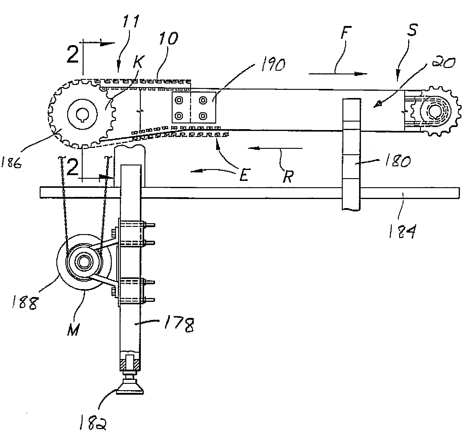
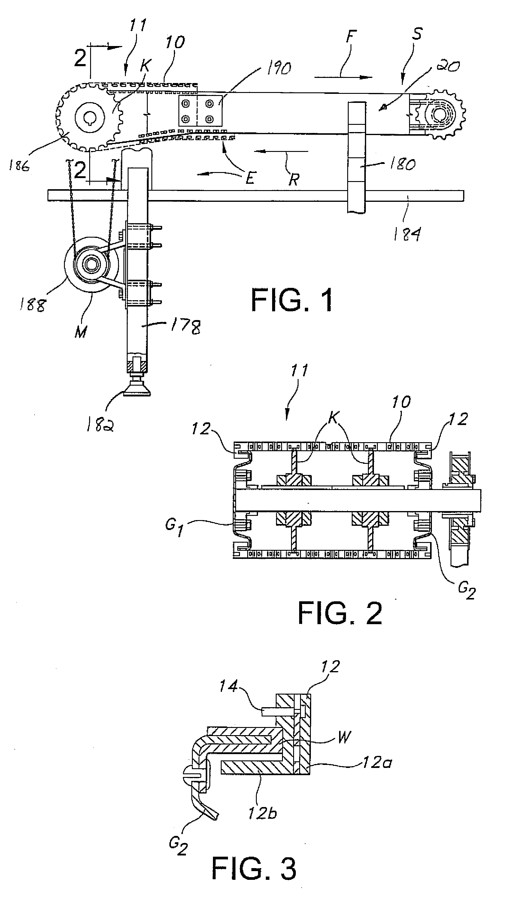
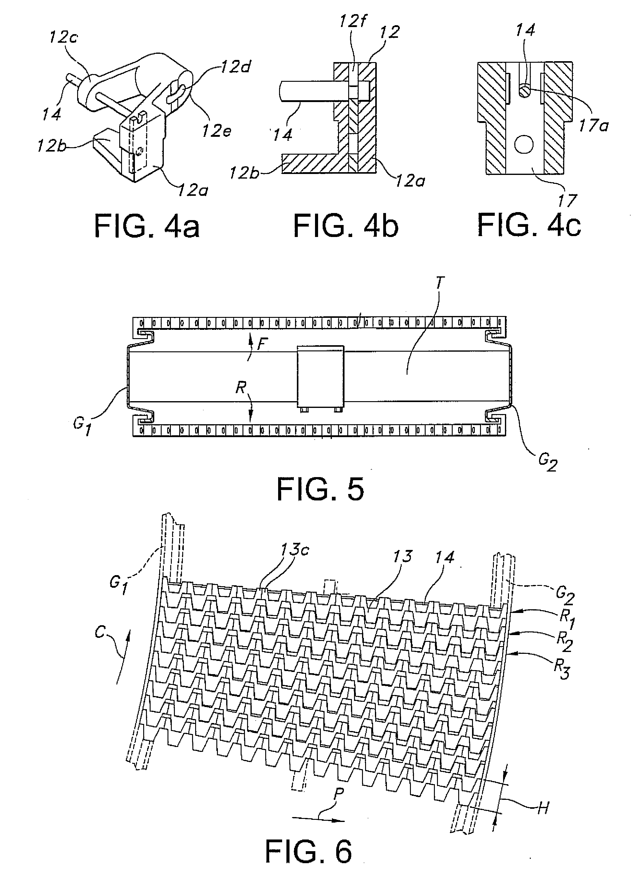
[0041]Reference is now made to FIGS. 1 and 2, which depict one possible environment in which the various disclosed aspects of the present invention may have utility. These figures depict an overall conventional arrangement of a conveyor system S including a belt or chain 10. The chain 10 includes a wear surface, such as conveying surface 11, for engaging and supporting articles. In this particular embodiment, the chain 10 comprises or includes modular links including side guide links 12 and intermediate links 13 arranged in spaced apart rows (see FIG. 6 and note rows R1 . . . Rn), which thus partially create the conveying surface 11. Adjacent rows R1, R2 of links are interconnected by transversely extending connectors 14.

[0042]With regard to the side links 12, and as perhaps best understood by viewing FIGS. 3 and 4a-4c, each may include an outer depending arm 12a and an inwardly projecting or extending transverse tab 12b (thus creating different right handed or left handed side link...


PUM


Abstract

A component subjected to wear during use includes a powder coating formed of a polymer selected from the group consisting of a polyamide, polyolefin, polyester, urethane, epoxy, acrylic, and mixtures thereof to provide improved wear resistance, enhanced cleanability, and reduced surface friction. Preferably, the component is for use in conveying product, such as in a conveyor system, and includes: (1) a metal core and a nylon powder coating; or (2) a stainless steel core and a powder coating. Most preferably, the coating is generally clear or translucent so as to give the appearance that the underlying component, which is typically made of metal, is neither coated nor made entirely of a polymer.

Description

[0001]This application claims the benefit of U.S. Provisional Patent Application Ser. No. 60 / 788,650, filed Apr. 3, 2006, the disclosure of which is incorporated herein by reference.TECHNICAL FIELD[0002]This invention relates generally to the tribological arts and, more particularly, to wear-resistant, easily cleanable powder coated components with low friction surfaces, especially for use in conveying product.BACKGROUND OF THE INVENTION[0003]The use of metal, such as steel, in forming wear components is ubiquitous. To provide steel components with enhanced surface properties and wear resistance, one very popular technique is to alter the composition of the steel alloy during fabrication to provide an outer surface with high corrosion resistance. Besides being resistant to troublesome corrosion and staining, this “stainless” steel as it is commonly known provides low maintenance and is relatively inexpensive to fabricate, which makes it an ideal base material for a host of commercia...

Claims


Application Information

Patent Timeline
IPC IPC(8): B65G15/62B65G17/06B05D1/06B05D1/12
CPCB65G17/086B65G2207/48B65G2207/26B65G2201/0202
Inventor RUSSELL, MARK D.
Owner SPAN TECH
Learn More