Cartridge pistol with a cartridge holder

a cartridge gun and cartridge technology, applied in the direction of containers, liquid/fluent solid measurement, volume measurement, etc., can solve the problems of difficult to achieve precise dosing and apportionment of pasty materials, pressure builds up in cartridges, etc., to achieve low overall weight of cartridge guns, simple exchange of cartridges, and the effect of low material conten

Active Publication Date: 2009-09-03
RAY TECHNOLOGY GROUP BV
View PDF2 Cites 17 Cited by
  • Summary
  • Abstract
  • Description
  • Claims
  • Application Information

AI Technical Summary

Benefits of technology

[0008]A cartridge gun comprising a cartridge holder is provided. The inventive cartridge gun requires little material and allows a simple exchange of cartridges. The cartridge gun comprises a piston rod and a base in which the lower end of a cartridge is insertable. Gripping elements are arranged in the base which engage the inside wall of the inserted cartridge and hold the cartridge. To release the gripping elements, the piston rod is withdrawn completely from the cartridge until a stamp arranged at the front end of the piston rod presses back the gripping elements from the gripping position and releases the cartridge for removal. The advantage of such a cartridge gun is that the cartridge receiver, comprising a base, does not extend over the entire length of the cartridge to be inserted therein. Material is saved by omitting a shell construction for the cartridge holder. The overall weight of the cartridge gun can thus be kept low. The cartridge gun further comprises an actuating device for displacing the piston rod, which allows the displacement of the piston rod in a continuous manner, alternating in the forward direction or in the reverse direction. A stamp, comprising a rearward projecting stamp, is arranged at the front end of the piston rod. To remove a used or empty cartridge, the stamp is retracted with the piston rod until the edge of the stamp rests on the gripping elements arranged in the base of the cartridge holder. The retraction of the stamp can be achieved either by pulling at the rear end of the piston rod or by multiple pressing of a retraction lever, which displaces the piston rod in a rearward direction. By pressing the retraction lever, the stamp presses against the gripping elements and detaches the gripping e

Problems solved by technology

One problem with conventional cartridge guns or presses is that a pressure builds up within the cartridge during the advancement of the stamp, which is attached to the piston rod.
After the emission of the pasty material within the

Method used


Image

  • Cartridge pistol with a cartridge holder
  • Cartridge pistol with a cartridge holder
  • Cartridge pistol with a cartridge holder

Examples


Embodiment Construction

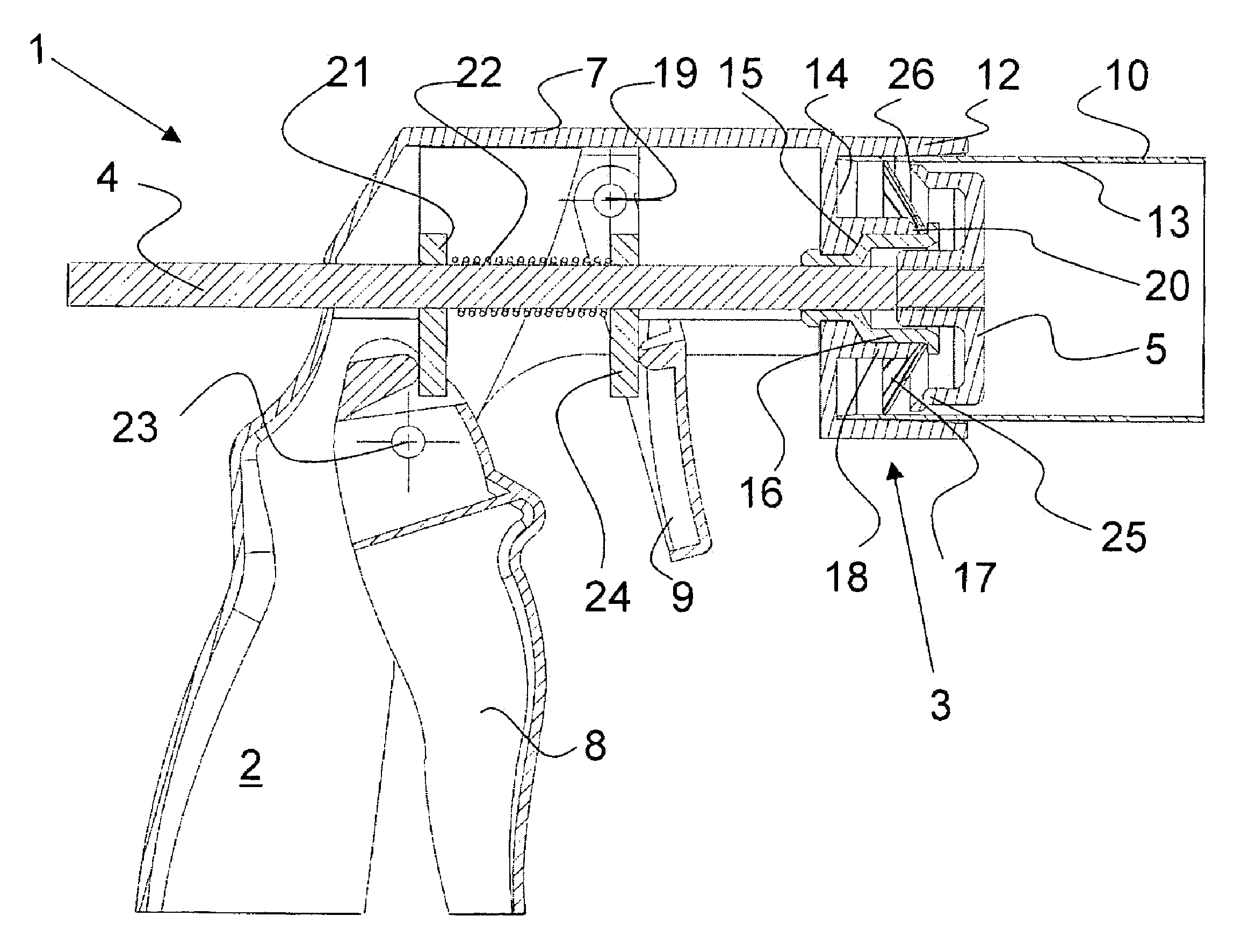
[0015]A cartridge gun comprising a cartridge holder is provided. The inventive cartridge gun has the advantages of weighing lighter than cartridge guns or presses known in the art and being able to substantially eliminate the subsequent dripping of materials released from the cartridge due to the pressure build-up within the cartridge when the cartridge is pressed.

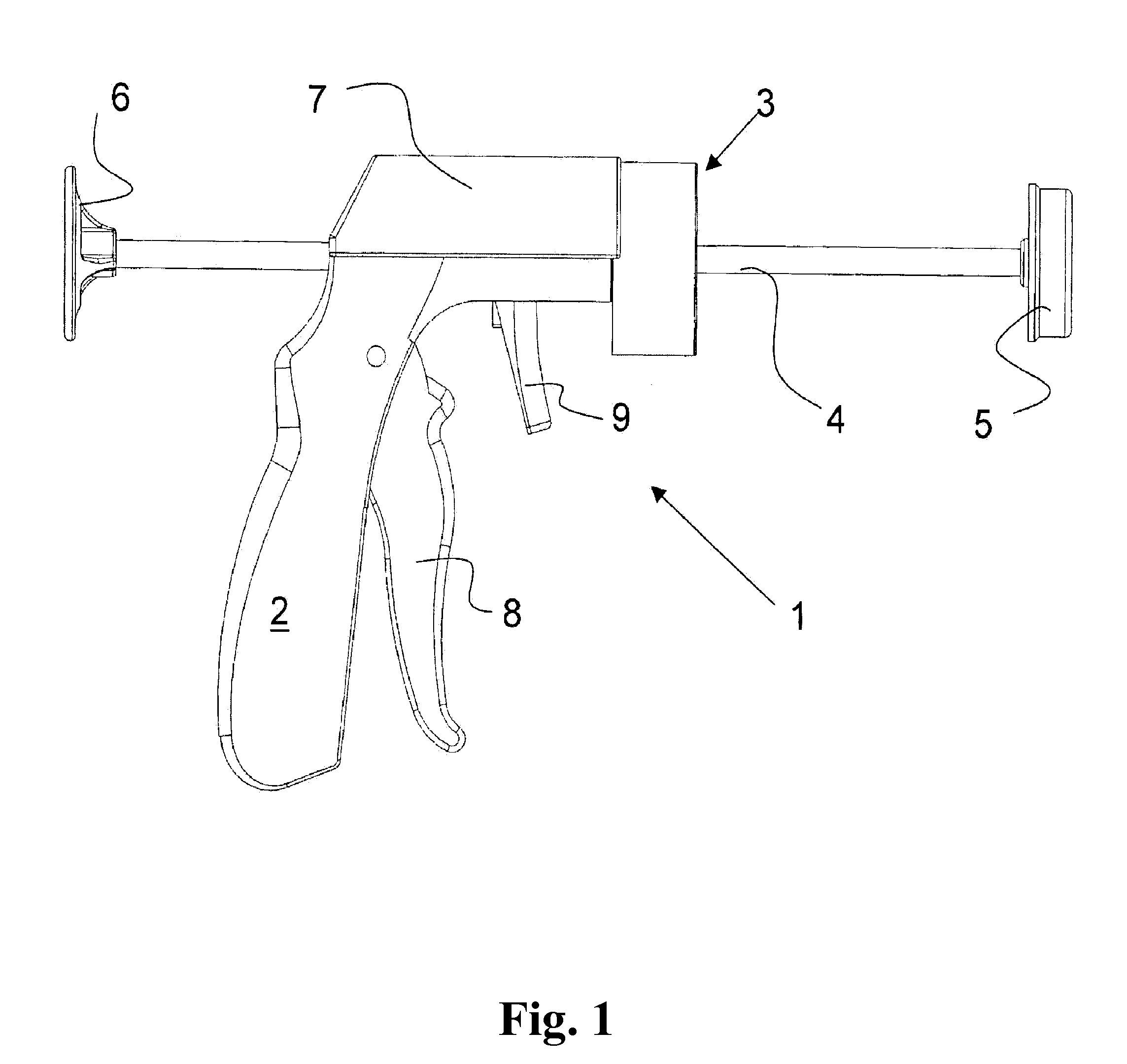
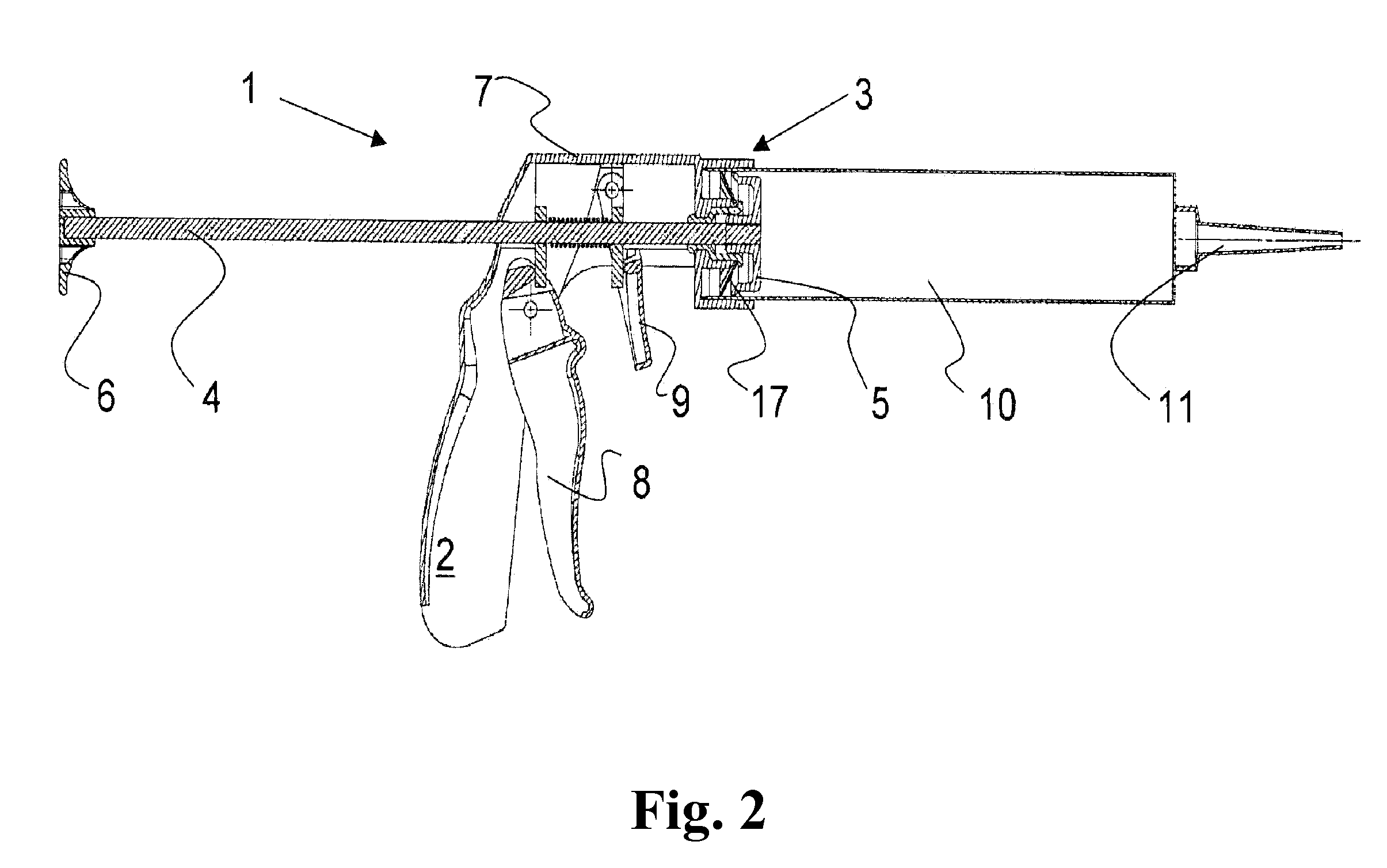
[0016]FIG. 1 shows a side view of an embodiment of a cartridge gun 1. The cartridge gun 1 comprises a housing 7, a grip 2, and a cartridge holder 3. The housing 7 comprises a piston rod 4, and an advancement and retraction device for displacing the piston rod 4 is arranged in the housing 7, and the device can be actuated by way of a pressure or advancement trigger 8. The piston rod 4 is moved forward a short step towards the front of the cartridge gun 1 with each pressure movement on advancement trigger 8, and it is moved a short step backward towards the rear of the cartridge gun 1 following a pressure movement of a retra...


PUM


Abstract

A cartridge gun is provided. The cartridge gun comprises a cartridge holder, a plurality of resilient gripping elements, a displaceable piston rod for moving a piston in a cartridge, and an actuating device for displacing the piston rod. The cartridge holder comprises a cylindrical base for receiving the floor region of the cartridge in which the gripping elements project radially outwardly from the center of the cartridge holder in the direction towards the housing into an annular groove of the base up to the outside wall of the annular groove in the base and are held in the center of the base by means of a hub. Means are further arranged at the front end of the piston rod which are designated to press the ends of the resilient gripping elements in the direction towards the housing when the piston rod is fully retracted, allowing the removal of the cartridge from the cartridge gun.

Description

CROSS REFERENCE TO RELATED APPLICATIONS[0001]This application claims priority under 35 U.S.C. §365(a) to International Patent Application No. PCT / IB2005 / 000947, filed Apr. 6, 2005, and under 35 U.S.C. §120 to International Patent Application No. PCT / IB2005 / 000947, filed Apr. 6, 2005, which claims priority to Swiss Patent Application No. 00619 / 04, filed Apr. 8, 2004.FIELD OF THE INVENTION[0002]The invention generally relates to a cartridge gun with a cartridge holder.BACKGROUND OF THE INVENTION[0003]Cartridge guns, also known as cartridge presses, are known in the art, and may be used for pressing out pasty materials from cartridges, e.g. sealing materials, adhesive materials, and the like. In general, these cartridge presses comprise a shell for receiving a cartridge wherein the shape of the shell matches the external shape of the cartridge. One side of the shell is fastened to the handle of the cartridge press and comprises a recess in which a pressure rod with the stamp attached t...

Claims


Application Information

Patent Timeline
IPC IPC(8): B05C17/01B67D5/42B05C17/005B67D7/60
CPCB05C17/00576B05C17/014B05C17/0123B05C17/01
Inventor DE MAN, EELCO H.VAN SWIETEN, ROY
Owner RAY TECHNOLOGY GROUP BV
Why Eureka
Try Eureka