Organic electroluminescence device

Inactive Publication Date: 2009-09-03
UDC IRELAND
View PDF12 Cites 19 Cited by
  • Summary
  • Abstract
  • Description
  • Claims
  • Application Information

AI Technical Summary

Benefits of technology

[0009]An object of the invention is to provide a luminescence device l

Problems solved by technology

However, devices that satisfy driving voltage, efficiency and durability are not yet obtained even with these techniques.
For the improvement of light emitting efficiency, an organic luminescence device having a light-emitting layer consisting of only a material comprising a light-emitting material and a single bond alone is described in JP-A-2006-120811 (The term “JP-A” as us

Method used


Image

  • Organic electroluminescence device
  • Organic electroluminescence device
  • Organic electroluminescence device

Examples


Example

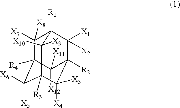
[0025]The organic electroluminescence device in the invention (hereinafter sometimes referred to as “the device in the invention”) is an organic electroluminescence device comprising a pair of electrodes and at least one organic layer (which may be a layer comprising an organic compound alone or may be a layer containing an organic compound and an inorganic compound) including a light-emitting layer between the pair of electrodes, and at least any one of the at least one organic layer contains both at least one hydrocarbon compound having an alkyl structure and a charge transporting material.

[0026]In general, it is known that in charge (electron / hole) injection at organic film interface of a lamination type organic electronic device, when the difference in ionization potentials (Ip) each other and electron affinities (Ea) each other of contiguous two materials is small, barrier of charge injection is small, and driving voltage of an organic electroluminescence device can be reduced,...


PUM


Abstract

Provided is an organic electroluminescence device including: a pair of electrodes; and at least one organic layer including a light-emitting layer being provided between the pair of electrodes, wherein at least any one of the at least one organic layer contains both at least one hydrocarbon compound having an alkyl structure and a charge transporting material.

Description

BACKGROUND OF THE INVENTION[0001]1. Field of the Invention[0002]The present invention relates to an organic electroluminescence device (hereinafter also referred to as “an organic EL device”, “luminescence device” or “device”) capable of converting electric energy to light and emitting light. Specifically the invention relates to an organic electroluminescence device excellent in driving voltage and EL external light emission efficiency.[0003]2. Description of the Related Art[0004]In recent years, studies and developments in connection with various displays using organic light-emitting materials (organic luminescence devices) have been actively advanced. Above all, organic EL devices are attracting public attention as promising displays for capable of emitting light of high luminance with low voltage.[0005]Further, in recent years, increment in efficiency of the devices has been advanced by the use of phosphorescent materials. As the phosphorescent materials, iridium complexes and p...

Claims


Application Information

Patent Timeline
IPC IPC(8): H01J1/63
CPCH01L51/006H01L51/0062H01L51/5016H01L51/5012H01L51/0087H10K85/649H10K85/633H10K85/346H10K50/11H10K2101/10H05B33/14C09K11/06
Inventor TAKEDA, AKIRATOBISE, MANABUSATOU, TASUKU
Owner UDC IRELAND
Why Eureka
Try Eureka