Positioning system for projecting a site model

a projecting system and site technology, applied in soil shifting machines/dredgers, optical elements, instruments, etc., can solve the problems of difficulty for operators to mentally transpose between, operator's work efficiency is reduced, and operators are difficult to look back and forth between display monitors

Inactive Publication Date: 2009-09-03
CATERPILLAR INC
View PDF13 Cites 28 Cited by
  • Summary
  • Abstract
  • Description
  • Claims
  • Application Information

AI Technical Summary

Problems solved by technology

One shortcoming of the above-described scheme is the difficulty operators have when looking back and forth between the display monitor and the actual worksite visible through the windows of his machine.
The display may show a large amount of precise plan lines, which may be difficult for an operator to mentally transpose between the display and the physical changes he is making to the worksite.
Additionally, continuously glancing back and forth between the display and the actual worksite for long periods of time may become mentally exhausting and may cause the operator to work less efficiently.
Although the method of the '576 patent may provide a method for displaying agricultural information for two-dimensional operations such as agricultural product placement, it may not provide a method for making calculations for three-dimensional operations and displaying the output from those calculations.
The method of the '576 patent may not be configured to display three-dimensional design plans associated with construction work.

Method used


Image

  • Positioning system for projecting a site model
  • Positioning system for projecting a site model
  • Positioning system for projecting a site model

Examples


Embodiment Construction

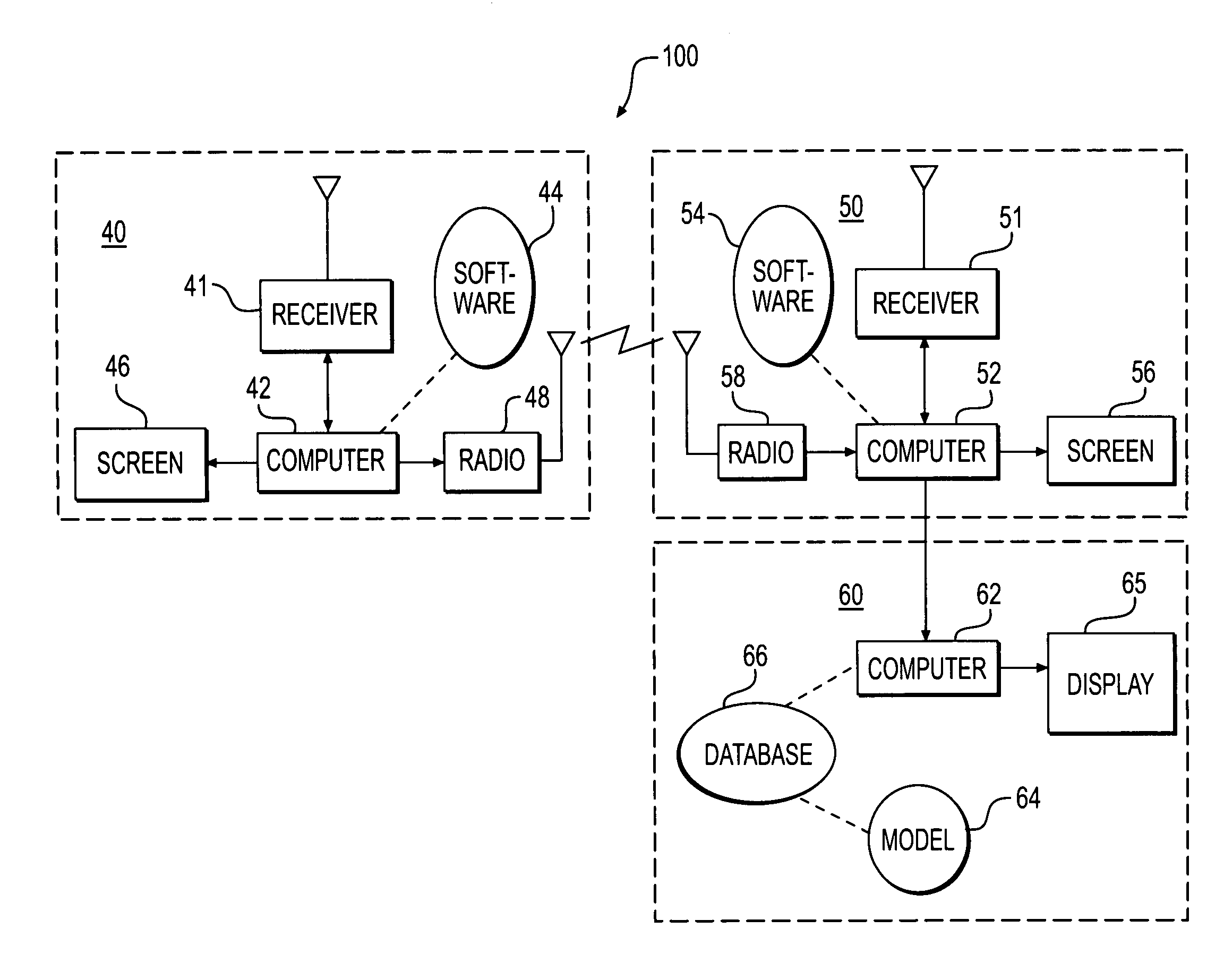
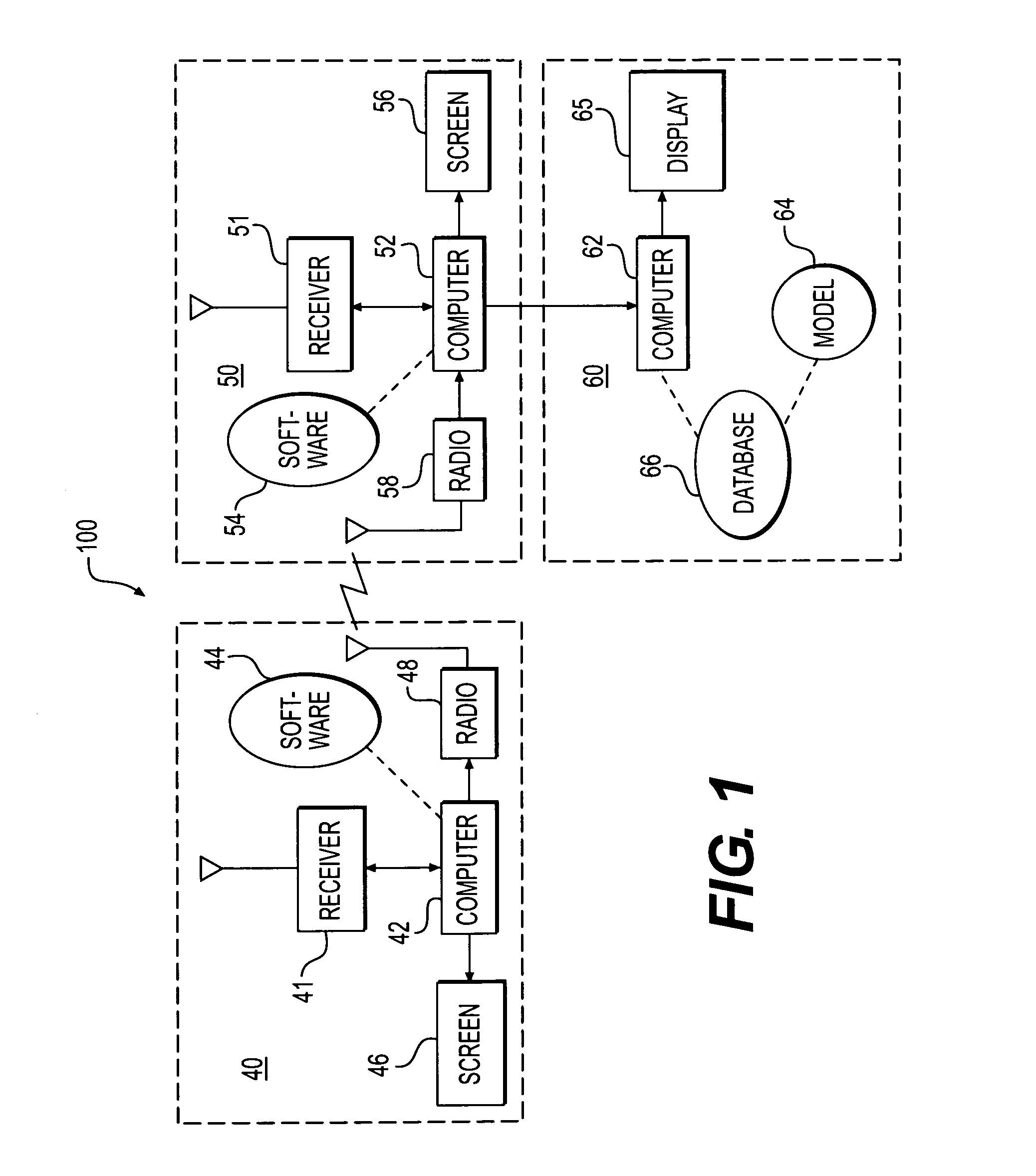
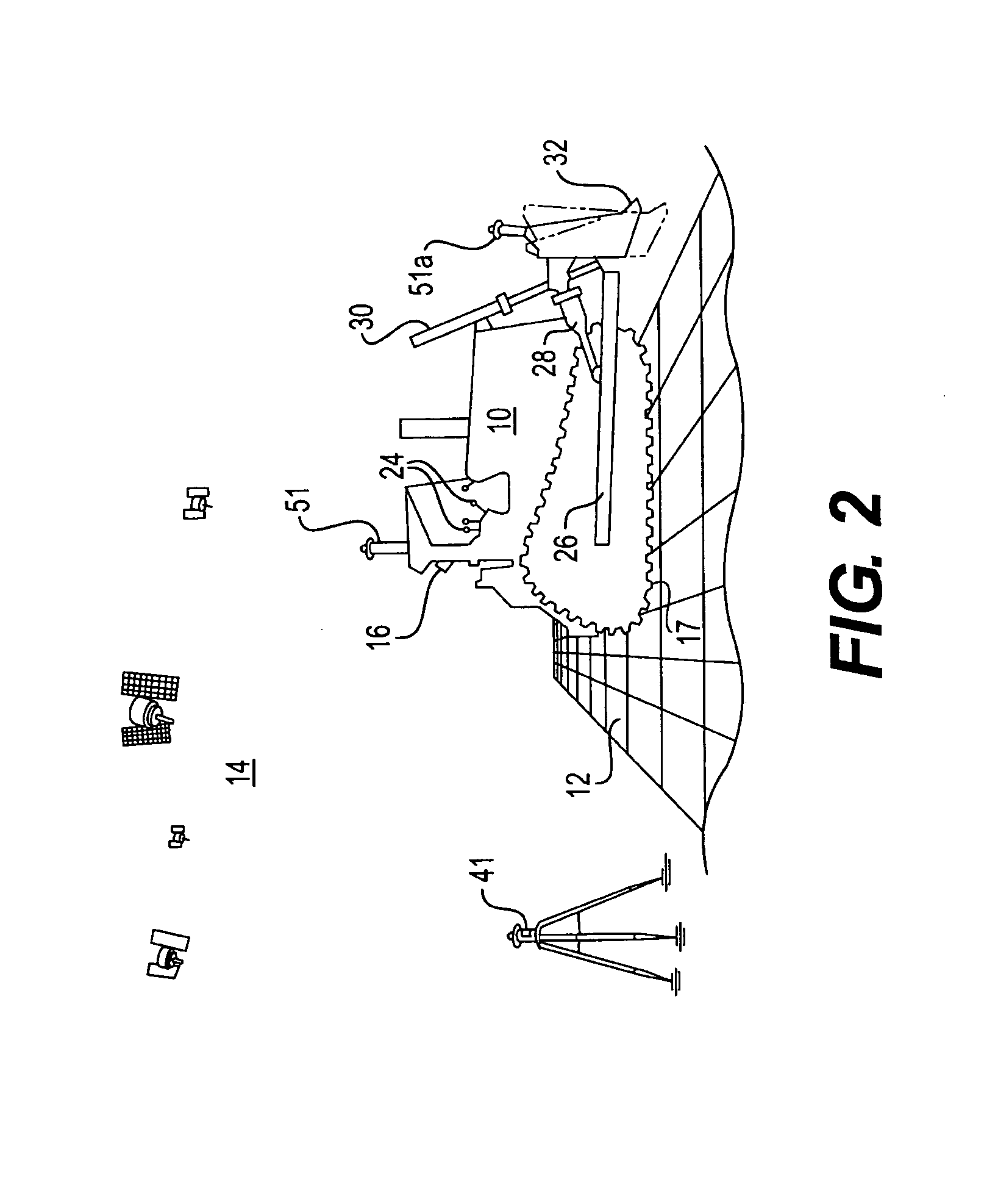
[0015]Referring to FIG. 1, a schematic of a three-dimensional positioning system 100 is shown. System 100 may use a differencing algorithm to calculate a machine position and path in real time. System 100 may include a base reference module 40, a position module 50, and an update module 60. Base reference module 40 may be located at a stationary position. Module 40 may be located in a permanent site such as, for example, a building or trailer. Module 40 may be located on a work site 12, or remotely from a work site 12. Module 50 and module 60 may be located on a machine such as, for example, a terrain-altering machine 10. Module 40 and module 50 may together be configured to determine three-dimensional coordinates of terrain-altering machine 10 relative to work site 12, while an update module 60 may convert these three-dimensional coordinates, e.g., position information, into real time representations of the site, which may be used to monitor and control machine 10.

[0016]Base refere...


PUM


Abstract

A positioning system is disclosed. The positioning system has a database for storing a site model. The site model has data indicative of a desired geography of a site environment and an actual geography of the site environment. The positioning system also has a first receiver for generating digital signals representing a real time position in three-dimensional space of at least a portion of a machine as the machine traverses the site environment. The positioning system further has a processor for receiving the signals and updating the site model to determine a difference between the data indicative of the desired geography and the data indicative of the actual geography. The positioning system also has a display for projecting the site model onto at least one surface of an operator station of the machine so that an operator may simultaneously view the site model and the site environment.

Description

TECHNICAL FIELD [0001]This disclosure relates generally to a positioning system and, more particularly, to a positioning system for projecting a site model.BACKGROUND [0002]The construction industry often employs computer systems for digitally mapping work sites, particularly for operations such as earth-moving. To facilitate digital mapping, construction personnel typically provide earth-moving machines with global positioning systems (GPS). As an alternative to employing standard surveying teams, construction personnel use a machine with GPS to produce an initial survey of a work site. The machine with GPS moves back and forth across a worksite, collecting three-dimensional GPS coordinates and providing the data to a computer. The computer, which may be located on board of the machine or located remotely, inputs the data into a software application or algorithm to create a three-dimensional model of the actual contours of the worksite. This model provides the initial survey of the...

Claims


Application Information

Patent Timeline
Patent Type & Authority Applications(United States)
IPC IPC(8): G01S5/00G06T15/00G01S19/48
CPCE02F9/2025E02F9/26G01C15/00G06T17/05G02B27/01G02B2027/014G01S19/43E02F9/261
Inventor BORCHERT, JOANNE CHARLOTTEFOUTS, STEPHEN RAY
Owner CATERPILLAR INC
Why Eureka
Try Eureka