Image capturing system and computer readable recording medium for recording image processing program

a technology of image processing and image capturing system, which is applied in the field of image capturing system and computer readable recording medium for recording image processing program, can solve the problems of white noise, noise characteristics, random noise in the image capturing device and the analog circuit, etc., and achieve the effect of noise reduction processing

Active Publication Date: 2009-09-03
OLYMPUS CORP
View PDF7 Cites 39 Cited by
  • Summary
  • Abstract
  • Description
  • Claims
  • Application Information

AI Technical Summary

Benefits of technology

[0012]An image capturing system according to one aspect of the present invention is an image capturing system which performs noise reduction processing on an image signal acquired from an image capturing unit. The image capturing system includes: local region extracting means which extracts, from the image signal, a local region including a target pixel to be subjected to the noise reduction processing and at least one neighboring pixel positioned spatially in the vicinity of the target pixel; first noise reducing means which performs adaptive noise reduction processing on the target pixel within the local region; noise estimating means which estimates the noise amount with respect to the target pixel based upon the target pixel value subjected to the noise reduction processing by the first noise reducing means; and second noise reducing means which performs noise reduction processing on the target pixel based upon the target pixel value subjected to the noise reduction processing by the first noise reducing means and the noise amount estimated by the noise estimating means.
[0013]Also, a computer readable recording medium for recording an image processing prog

Problems solved by technology

The aforementioned fixed pattern noise is noise that occurs principally due to the image capturing device, typical examples of which include noise due to defective p

Method used


Image

  • Image capturing system and computer readable recording medium for recording image processing program
  • Image capturing system and computer readable recording medium for recording image processing program
  • Image capturing system and computer readable recording medium for recording image processing program

Examples


embodiment 1

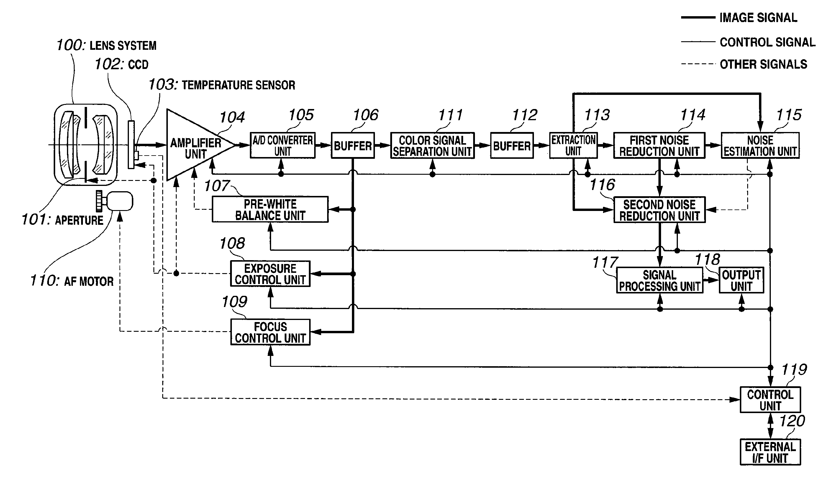
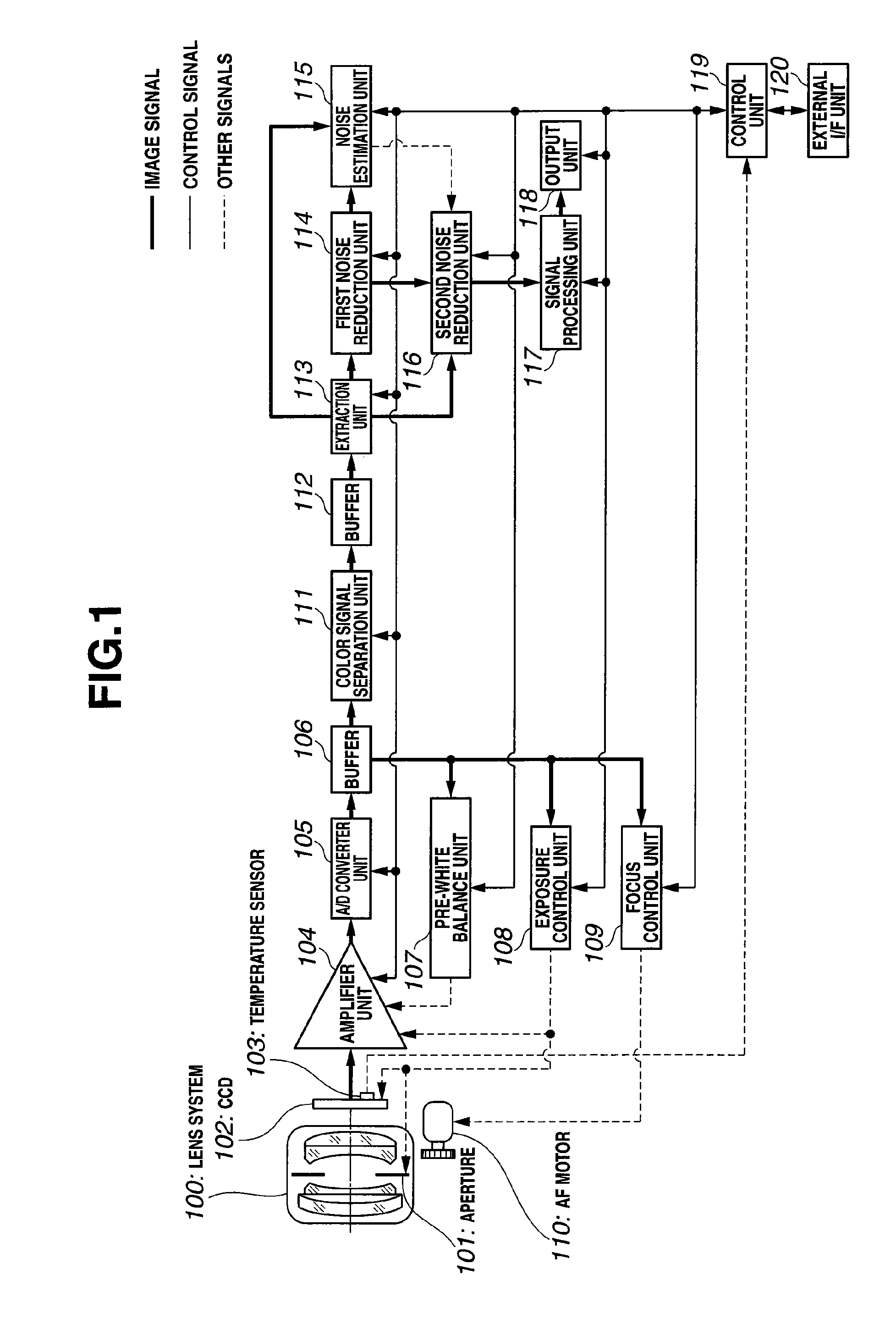
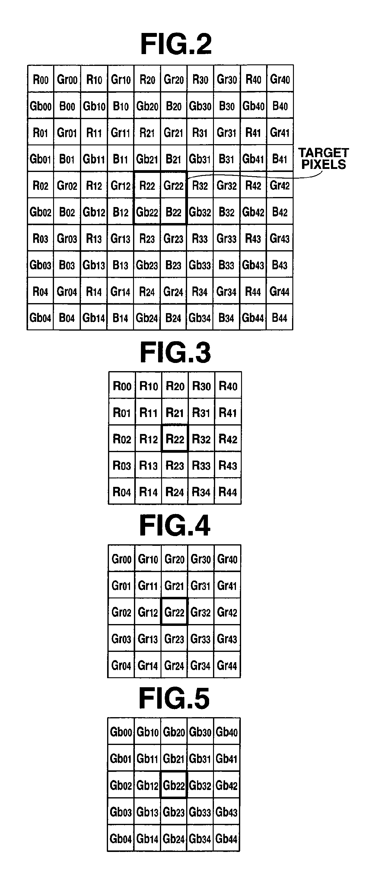
[0068]FIG. 1 through FIG. 24 show an embodiment 1 according to the present invention. FIG. 1 is a block diagram which shows a configuration of an image capturing system. FIG. 2 is a diagram which shows a pattern of a Bayer-type primary color filter. FIG. 3 is a diagram which shows the R-color signal extracted from a local region. FIG. 4 is a diagram which shows the Gr-color signal extracted from a local region. FIG. 5 is a diagram which shows the Gb-color signal extracted from a local region. FIG. 6 is a diagram which shows the B-color signal extracted from a local region. FIG. 7 is a diagram which shows a pattern of a color-difference line-sequential type complementary color filter for a local region. FIG. 8 is a diagram which shows the Cy-color signal extracted from a local region. FIG. 9 is a diagram which shows the Ye-color signal extracted from a local region. FIG. 10 is a diagram which shows the G-color signal extracted from a local region. FIG. 11 is a diagram which shows the...

embodiment 2

[0244]FIG. 25 through FIG. 36 show an embodiment 2 according to the present invention. FIG. 25 is a block diagram which shows a configuration of an image capturing system. FIGS. 26A to 26C are diagrams for describing the pattern of a color-difference line-sequential type complementary color filter, a field signal output by performing two-pixel mixing processing, and a local region. FIGS. 27A to 27D diagrams for describing separation of an even-numbered field signal shown in FIG. 26B into a GCy-color signal, a MgYe-color signal, a MgCy-color signal, and a GYe-color signal. FIG. 28 is a block diagram which shows a configuration of a first noise reduction unit. FIG. 29 is a diagram for describing directionally-divided regions divided by a region dividing unit. FIG. 30 is a block diagram which shows a configuration of a noise estimation unit. FIG. 31 is a block diagram which shows a configuration of a second noise reduction unit. FIGS. 32A and 32B are diagrams for describing neighboring...

embodiment 3

[0353]FIG. 37 through FIG. 53 show an embodiment 3 according to the present invention. FIG. 37 is a block diagram which shows a configuration of an image capturing system. FIG. 38 is a diagram which shows a pattern of a color filter for a first CCD with respect to a local region. FIG. 39 is a diagram which shows a pattern of a color filter for a second CCD with respect to a local region. FIG. 40 is a diagram which shows an R-color signal in the local region obtained by performing interpolation processing on the output of the second CCD. FIG. 41 is a diagram which shows a B-color signal in the local region obtained by performing interpolation processing on the output of the second CCD. FIG. 42 is a diagram which shows a Y signal in the local region obtained by separating the G signal shown in FIG. 38, the R signal shown in FIG. 40, and the B signal shown in FIG. 41. FIG. 43 is a diagram which shows a Cb signal in the local region obtained by separating the G signal shown in FIG. 38, ...


PUM


Abstract

An image capturing system includes: a first noise reduction unit which roughly removes the effects of an edge component by performing edge-preserving adaptive noise reduction processing on a target pixel within a local region including the target pixel and the neighboring pixels extracted from an image signal acquired from a CCD; a noise estimation unit which dynamically estimates the noise amount with respect to the target pixel based upon the target pixel value thus subjected to the noise reduction processing by the first noise reduction unit; and a second noise reduction unit which performs noise reduction processing on the target pixel based upon the target pixel value thus subjected to the noise reduction processing by the first noise reduction unit and the noise amount thus estimated by the noise estimation unit.

Description

CROSS REFERENCE TO RELATED APPLICATION[0001]This application is a continuation application of PCT / JP2007 / 071088 filed on Oct. 30, 2007 and claims benefit of Japanese Application No. 2006-305916 filed in Japan on Nov. 10, 2006, the entire contents of which are incorporated herein by this reference.BACKGROUND OF INVENTION[0002]1. Field of the Invention[0003]The present invention relates to an image capturing system and a computer readable recording medium for recording an image processing program which performs noise reduction processing on an image signal acquired from an image capturing unit.[0004]2. Description of the Related Art[0005]An image capturing unit comprises an image capturing device, and an analog circuit, an A / D converter and so forth, which are provided as components associated with the image capturing device. In general, an image signal acquired by an image capturing unit includes noise components. These noise components are roughly classified into fixed pattern noise...

Claims


Application Information

Patent Timeline
IPC IPC(8): H04N5/217G06T5/00G06T5/20H04N5/232H04N101/00
CPCG06T3/4015G06T5/20H04N5/21G06T2207/20192H04N9/045G06T5/002G06T2207/10024H04N5/357H04N25/60H04N25/136H04N23/843H04N25/134
Inventor TSURUOKA, TAKAO
Owner OLYMPUS CORP
Why Eureka
Try Eureka