Wavelength selective switch with reduced chromatic dispersion and polarization-dependent loss

a selective switch and chromatic dispersion technology, applied in the field of optical communication, can solve the problems of reducing affecting the performance of individual components, and the risk of excessive distortion of optical signals, so as to reduce the chromatic dispersion and/or low polarization-dependent loss, increase the fiber port capacity and optical performance of the wss, and reduce the performance requirements of individual components

Inactive Publication Date: 2009-09-03
OLYMPUS CORP
View PDF81 Cites 29 Cited by
  • Summary
  • Abstract
  • Description
  • Claims
  • Application Information

AI Technical Summary

Benefits of technology

[0014]Briefly described in a preferred embodiment, the present invention overcomes the above-mentioned disadvantages and meets the recognized need for such a system by providing a wavelength selective switch (WSS) with reduced chromatic dispersion and/or low polarization-dependent loss and uti

Problems solved by technology

For very long links, the optical signal risks becoming excessively distorted due to fiber-related impairments, such as, chromatic and polarization dispersion, and by noise limitations of the amplifiers, and may be reconstituted by detecting and re-launching the signal back into the fiber.
However, the same issues about signal degradation and OEO regeneration exist for WDM as with non-WDM fiber links.
The expense of OEO regeneration is compounded by the large number of wavelengths present in WDM systems.
Modern fiber optic networks are evolving to be much more complicated than the simple point-to-point “long haul” systems described above.
However, the desire to switch fiber optic signals while still in their optical format, thereby avoiding expensive OEO regeneration to the largest extent possible, presents a new challenge to the switching problem.
This replication of expensive OEO components is currently slowing th

Method used


Image

  • Wavelength selective switch with reduced chromatic dispersion and polarization-dependent loss
  • Wavelength selective switch with reduced chromatic dispersion and polarization-dependent loss
  • Wavelength selective switch with reduced chromatic dispersion and polarization-dependent loss

Examples


Embodiment Construction

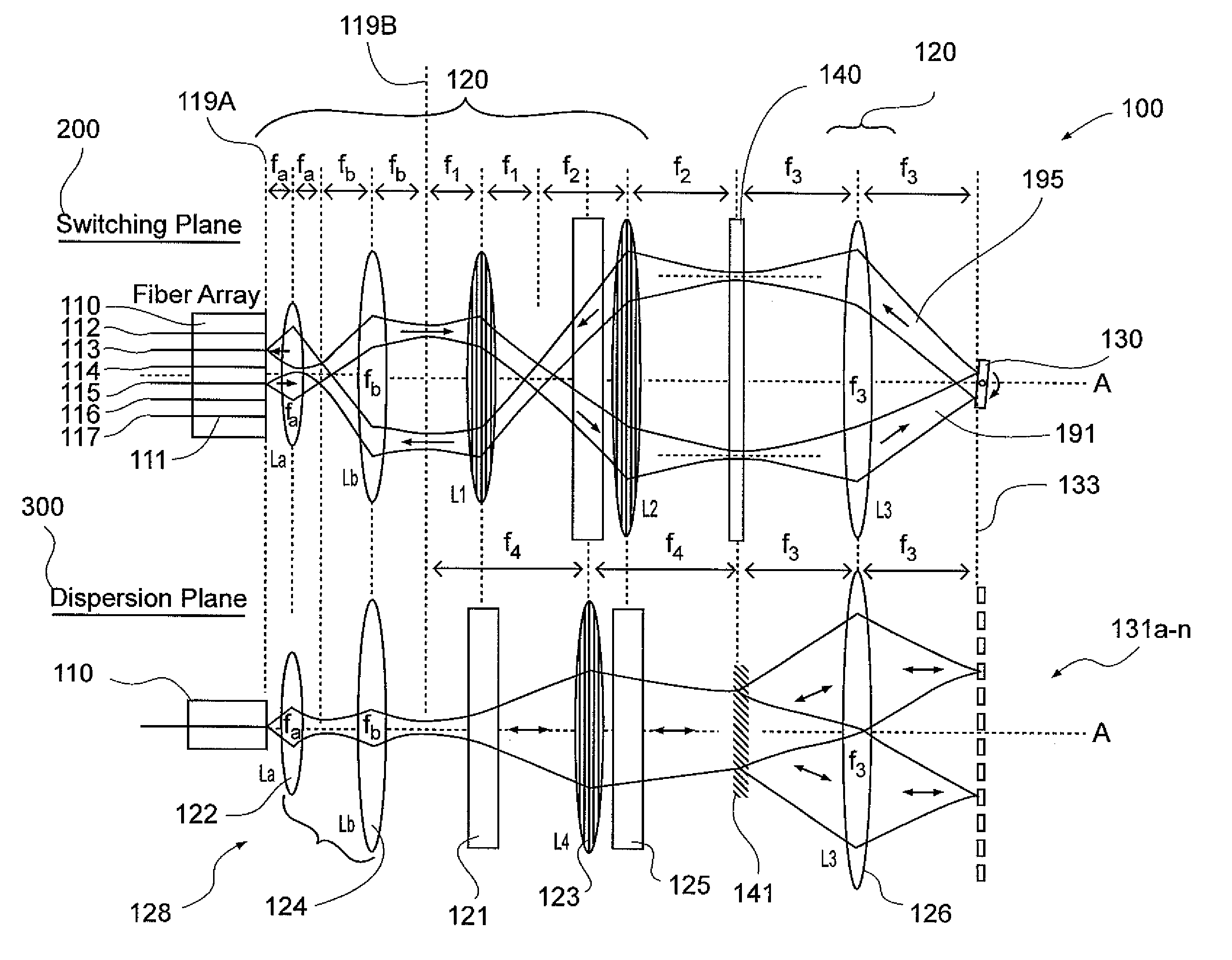
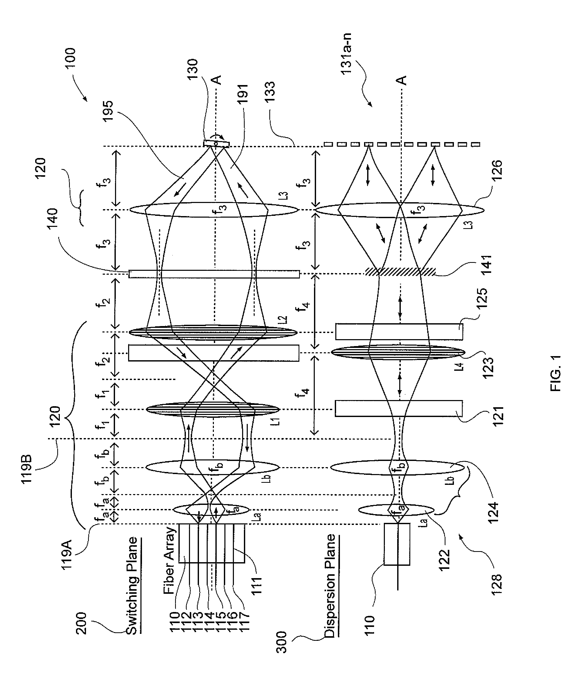
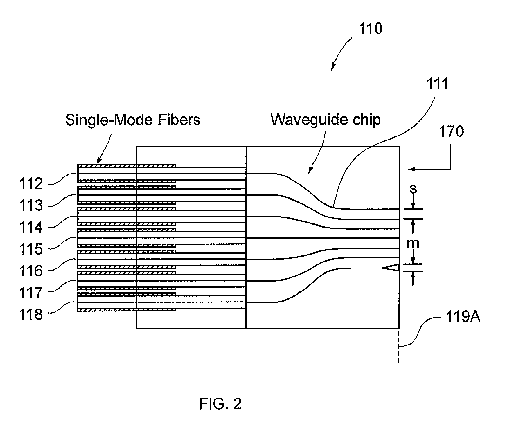
[0066]In describing the preferred embodiments of the present invention, as illustrated in the drawings, specific terminology is employed for the sake of clarity. The invention, however, is not intended to be limited to the specific terminology so selected, and it is to be understood that each specific element includes all technical equivalents that operate in a similar manner to accomplish a similar purpose.

[0067]For example, although the figures and description refer to single-element lenses, it should be understood that each such lens may be replaced by a plurality of elements, including one or more non-planar mirror(s), whereby the same function may be achieved. Such a plurality of elements may additionally offer enhanced performance characteristics. Moreover, such lens may be obtained by various techniques including but not limited to a single glass material, two or more glass materials in a compound fashion, a curved reflective surface, a diffractive surface, a holographic surf...


PUM


Abstract

A reduced polarization-dependent loss optical device utilizing two or more dispersive elements or a single dispersive element and a turning mirror, wherein the optical signal makes two passes through said single dispersive element when reflected from said turning mirror, and wherein the two or more dispersive elements or double pass single dispersive element has lower dispersion compared to a functionally equivalent single dispersive element, resulting in lower polarization dependent loss, reduced chromatic dispersion and increased wavelength dispersion. Moreover, a wavelength selective switch incorporating the optical device utilizing aperture-shared optics and functionally distinct planes of operation that enables high fiber port counts, such as 1×41, and multiplicative expansion, such as to 1×83 or 1×145, by utilizing elements optimized for performance in one of the functionally distinct planes of operation without affecting the other plane.

Description

PRIORITY CLAIM TO RELATED US APPLICATIONS[0001]To the full extent permitted by law, the present United States Non-Provisional patent application claims priority to and the full benefit of United States Provisional patent application entitled “Wavelength Selective Switch Having Distinct Planes of Operations”, filed on Feb. 28, 2008, having assigned Ser. No. 61 / 067,635 and United States patent application entitled “Wavelength Selective Switch Having Distinct Planes of Operations”, filed on Jul. 23, 2008, having assigned Ser. No. 12 / 220,356, incorporated entirely herein by reference.TECHNICAL FIELD[0002]The present invention relates generally to optical communications, and more specifically relates to wavelength division multiplexing.BACKGROUND OF THE INVENTION[0003]Modern communications networks are increasingly based on silica optical fiber which offers very wide bandwidth within several spectral wavelength bands. At the transmitter end of a typical point-to-point fiber optic communi...

Claims


Application Information

Patent Timeline
IPC IPC(8): G02B6/35G02B27/10
CPCG02B6/3544G02B6/3518
Inventor PRESLEY, HARRY WAYNENAGY, MICHAEL L.
Owner OLYMPUS CORP
Why Eureka
Try Eureka