Hot Runner Nozzle System

a nozzle system and hot runner technology, applied in the field of injection molding equipment, can solve the problems of abrasion of the two mating surfaces, catastrophic damage to the hot runner, and eventually wear or failure of the nozzle tip, so as to facilitate torquing, prevent resin leakage, and reduce the wall thickness of the retainer

Inactive Publication Date: 2009-09-03
HUSKY INJECTION MOLDING SYST LTD
View PDF6 Cites 26 Cited by
  • Summary
  • Abstract
  • Description
  • Claims
  • Application Information

AI Technical Summary

Benefits of technology

[0013]In accordance with the above aspects of the invention, there is provided a retainer, having a first retainer thread, which connects to a nozzle, having a nozzle thread, creating a first seal where the nozzle end of the retainer contacts the nozzle shoulder. The retainer has a plurality of flats thereon to facilitate torquing on to the nozzle thread. To prevent resin leakage beyond the gate insert of the mold, the retainer is configured to have a seal ring at its gate end such that, when heated, radial, thermal expansion of the outer diameter of the seal ring will make forced contact with the gate insert, thus precluding the passage of pressurized molten resin during operation. A second seal is created whereby the nozzle tip, having a tip t

Problems solved by technology

All these factors contribute to the nozzle tip eventually wearing out or failing thus necessitating its replacement, generally more frequently than most other components usually replaced during regular, periodic maintenance of the hot runner.
Though there is a nominal clearance between the two surfaces at room temperature, if disassembly is performed before the nozzle housing has cooled sufficiently from its operating temperature to reduce its radial, thermally-expanded diameter, or if the two surfaces are slightly misaligned, the result will be abrasion of the two mating surfaces.
Any slight scratches or abrasion of the seal ring on the nozzle housing may potentially provide a path for pressurized, molten resin to leak by, during operation, resulting in catastrophic damage to the hot runner.
Over time, this abrasion will require replacement of the entire n

Method used


Image

  • Hot Runner Nozzle System
  • Hot Runner Nozzle System
  • Hot Runner Nozzle System

Examples


Embodiment Construction

[0029]In the following detailed description, numerous specific details are set forth in order to provide a thorough understanding of the invention. However, it will be understood by those skilled in the art that the present invention may be practiced without these specific details. For example, well-known methods, procedures, and components have not been described in detail so as not to obscure the present invention.

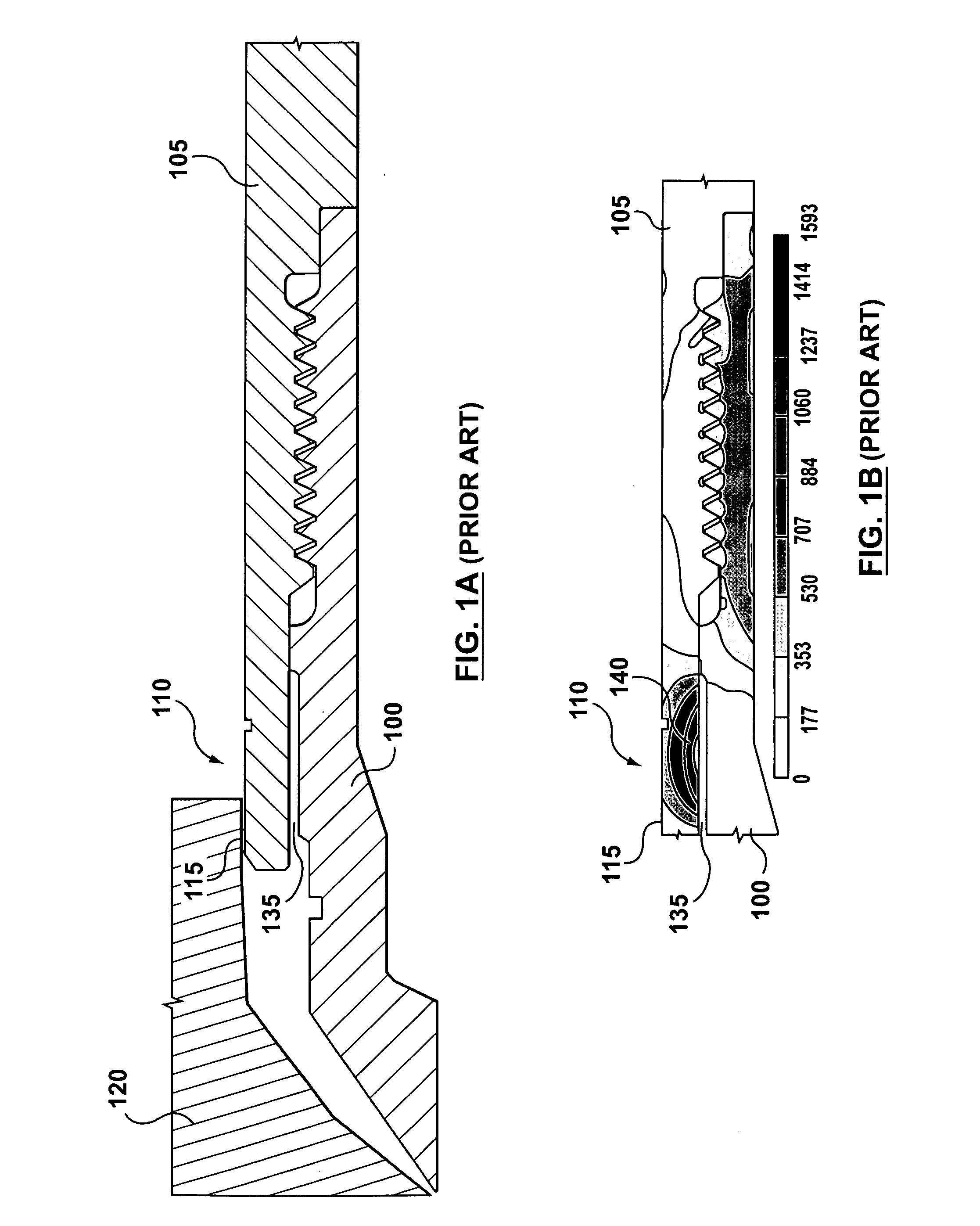
[0030]The prior art of FIG. 1A shows a nozzle tip 100 threadably engaged with a nozzle housing 105 for the purpose of understanding the function and interaction of each component. The nozzle housing 105 has a tip end 110 which is integral with the nozzle housing 105 in its entirety and therefore both aspects are made of one material suitable for the temperatures and pressures for which it is intended. Situated at the tip end 110 is a seal ring 115, being a precisely sized, raised band of material, the outer diameter of which thermally expands to contact a gate insert 120...


PUM

PropertyMeasurementUnit
Fractionaaaaaaaaaa
Pressureaaaaaaaaaa
Torqueaaaaaaaaaa

Abstract

A hot runner nozzle system (500) comprising a nozzle tip (100) adjacent to a nozzle (405) in series, and a retainer (400) adjoining both the nozzle tip (100) and the nozzle (405) in parallel, the retainer (400) having a first retainer thread (435), for connection to a nozzle thread (420) to form a first seal (450) between the nozzle end (440) of the retainer (400) and a nozzle shoulder (430), a second retainer thread (460), for connection to a tip thread (455) to form a second seal (470) between the inlet end (475) of the nozzle tip (100) and the gate end (425) of the nozzle (405), a seal ring (115) for creating a gate seal (496) with a gate insert (120), and a plurality of flats (410) thereon to facilitate torquing of the retainer (400) to the nozzle (405), the torque value applied to the retainer (400) being about two to four times of that applied to the nozzle tip (100) to facilitate removal of the nozzle tip (100) independent of the retainer (400).

Description

CROSS REFERENCES[0001]None.TECHNICAL FIELD OF THE INVENTION[0002]The present invention relates generally to the field of injection molding equipment and, more particularly, to a hot runner nozzle system whereby a nozzle tip and a retainer are threadably secured to a nozzle.BACKGROUND OF THE INVENTION[0003]A hot runner is utilized to transfer molten material, typically plastic resin, from an injection molding machine to a mold. A hot runner generally includes a manifold plate, a manifold housed in the manifold plate, and a backing plate that encloses the manifold in the manifold plate. The manifold, typically heated via a plurality of tubular heaters embedded therein, routes molten resin from a sprue bushing, which mates with an injection unit on an injection molding machine, to a plurality of nozzles which inject the molten resin into cavities in the mold. The manifold divides the flow of the molten resin into a network of a plurality of melt channels as it flows from the sprue bush...

Claims


Application Information

Patent Timeline
IPC IPC(8): B29C45/20
CPCB29C2045/2761B29C45/278
Inventor HAQUE, ZAKIUL
Owner HUSKY INJECTION MOLDING SYST LTD
Why Eureka
Try Eureka