
Liquid-Cooled Battery and Method for Operating Such a Battery

Inactive Publication Date: 2009-09-03
DAIMLER AG
View PDF5 Cites 50 Cited by
  • Summary
  • Abstract
  • Description
  • Claims
  • Application Information

AI Technical Summary

Benefits of technology

[0004]Furthermore, JP 10 241 739 A discloses a storage cell for a cooled battery, which likewise has a safety valve that opens above a specific temperature limit and has a cooling cartridge. The cooling cartridge itself once again also has a safety valve which is likewise opened, by means of the medium emerging from the safety valve of the storage cell, such that it can be activated thermally. This makes it possible to slightly cool down the emerging media. Owing to the comparatively small amount of cooling medium
[0006]The present invention provides a liquid-cooled battery, in particular as an energy store for an electrical drive in a motor vehicle, which allows good operating characteristics with a compact design which can be handled easily, and satisfies very stringent safety requirements.
[0009]The safety valve, which will typically be in the form of a flap, which can be opened via weak points, in the housing of the storage cells, is therefore responsible as a single, very reliable component for producing a safe battery state in the event of damage. The safety that can be achieved in this way is undoubtedly considerably better than in the case of comparable devices in which a chain of a plurality of components, some of which are complex, must be operated before a safe state can be achieved.
[0010]The battery according to the invention therefore ensures a simple design which can be implemented in a compact form and ensures a very high safety level by very simple passive means. This represents a considerable advantage, particularly when used in motor vehicles.

Problems solved by technology

This has the disadvantage that the hot and possibly explosive gases are passed to the area surrounding the battery, where they can possibly lead to damage, for example, a fire.

Method used


Image

  • Liquid-Cooled Battery and Method for Operating Such a Battery
  • Liquid-Cooled Battery and Method for Operating Such a Battery
  • Liquid-Cooled Battery and Method for Operating Such a Battery

Examples


Embodiment Construction

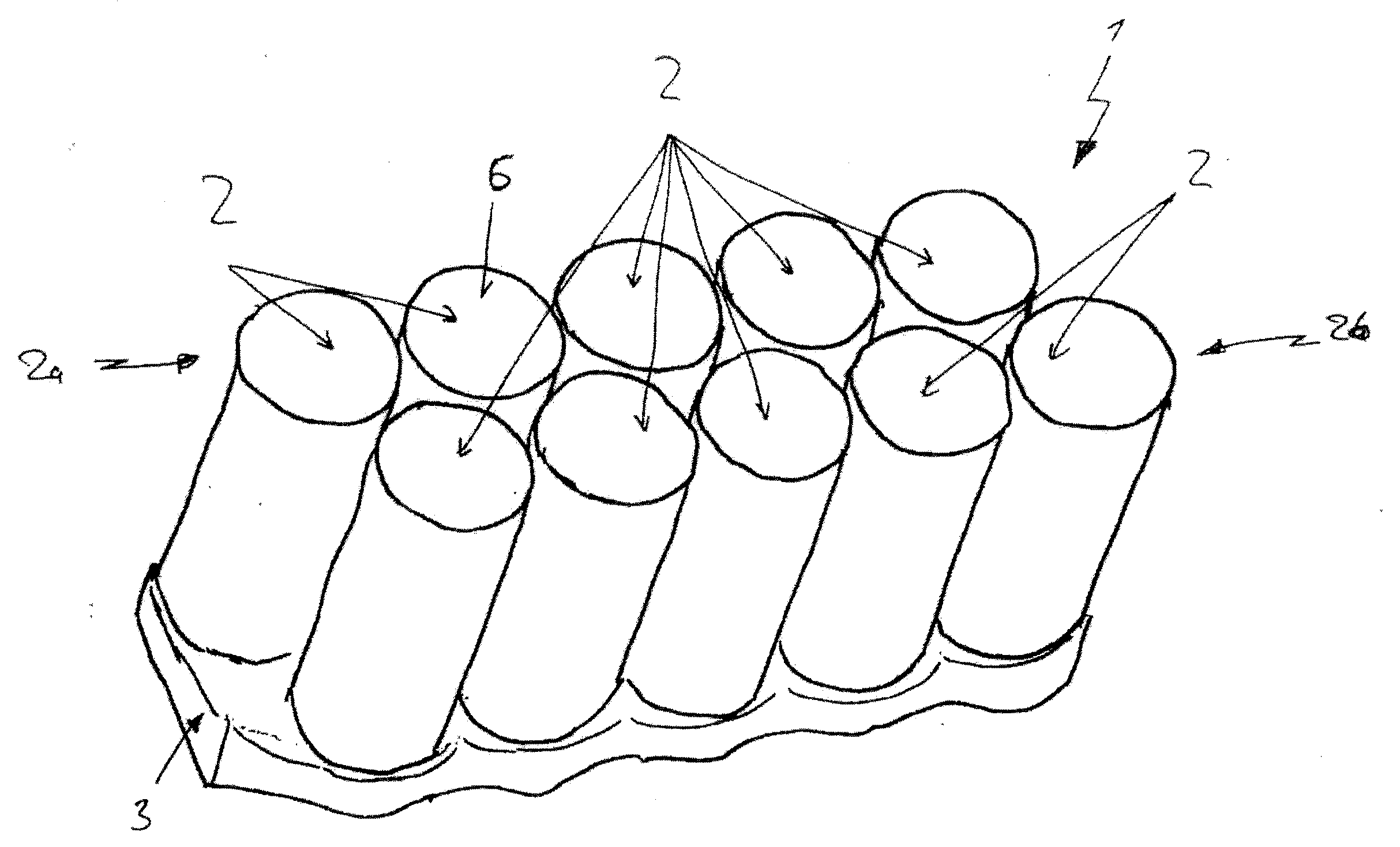
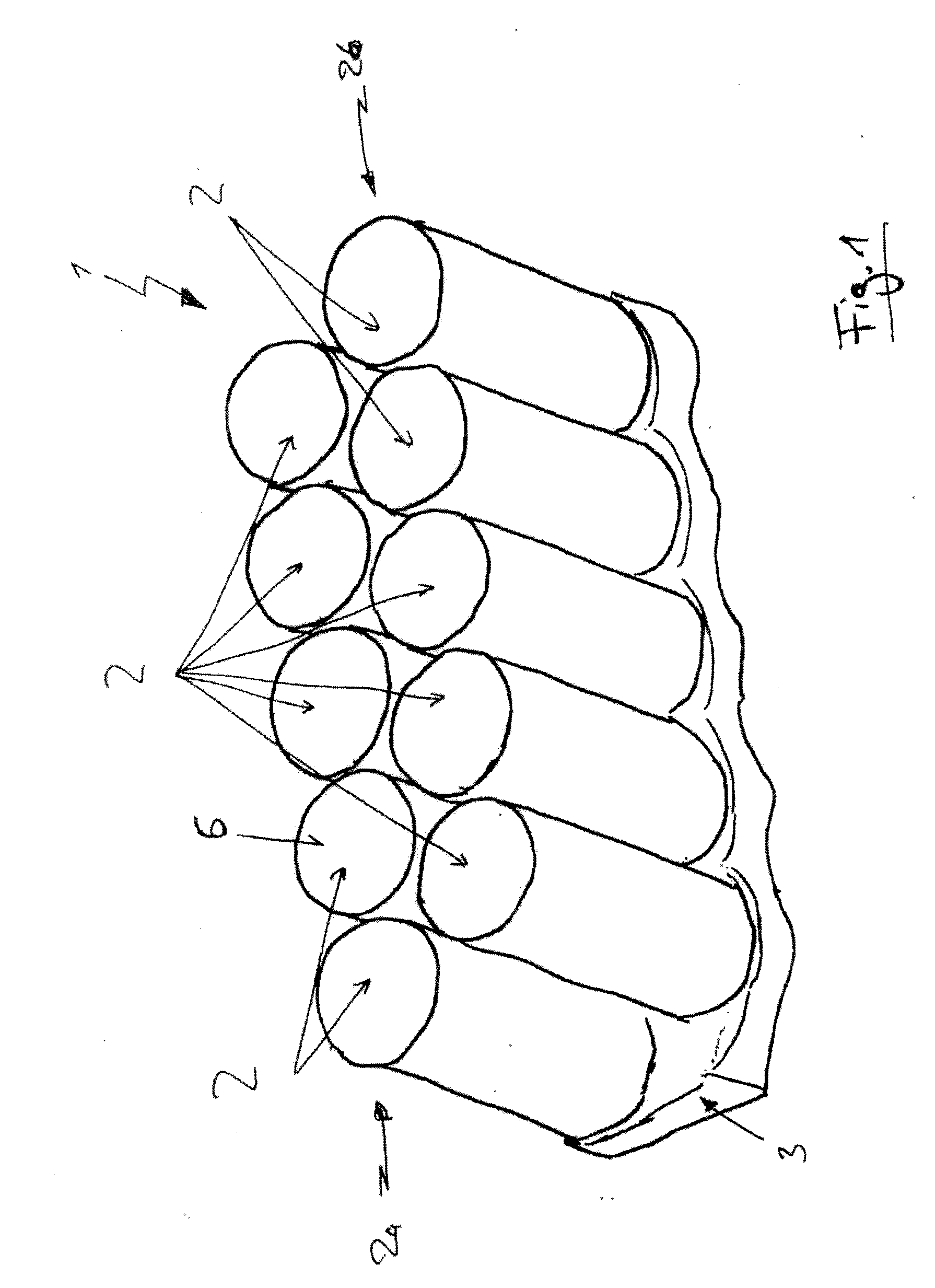
[0022]FIG. 1 schematically illustrates a battery 1. The battery 1 comprises a multiplicity of individual storage cells 2, which are arranged alongside one another in a plurality of rows 2a, 2b, in this case by way of example two rows 2a, 2b. The two rows 2a, 2b are in this case arranged offset with respect to one another, such that respectively adjacent rows 2a, 2b are shifted with respect to one another through half of the distance between the center lines of the individual storage cells 2 in one row. This allows the rows 2a, 2b to be packed very densely with respect to one another. Overall, this results in the battery 1 having a very compact design.

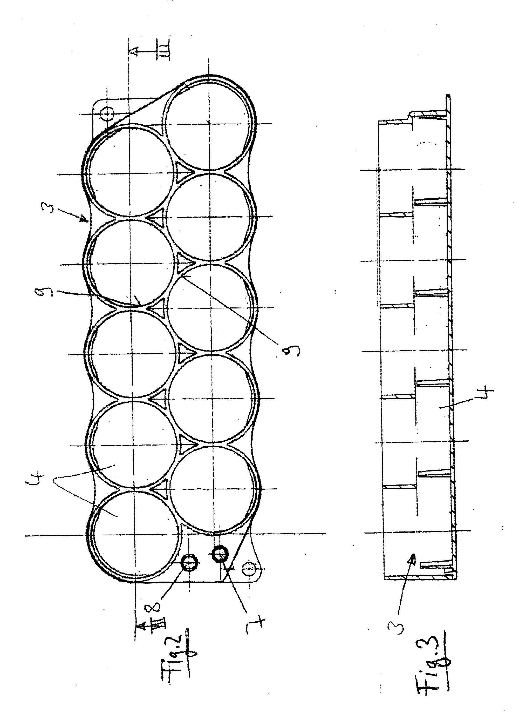
[0023]The battery is also cooled via a cooler 3 which has a volume 4 (although cannot be seen here) through which the cooling medium can flow and does flow during normal use. The individual storage cells 2 make thermally conductive contact with this cooler 3 on, in each case, one of their end faces (although this cannot be seen here). T...


PUM


Abstract

A liquid-cooled battery, in particular in the form of an energy store for an electrical drive in a motor vehicle is provided. The battery has a plurality of storage cells 2 and at least one volume 4 which makes thermally conductive contact with the storage cells 2 and through which a cooling medium can flow. Each of the storage cells 2 has a safety valve 12 which opens the storage cell when a predetermined media pressure in it is exceeded, and connects the volume of the storage cell to the surrounding area. The safety valve 12 is arranged in the storage cell 2 and the storage cell 2 is arranged with respect to the volume 4 through which the cooling medium can flow such that a connection is produced between the volume 4 through which the cooling medium can flow, and the interior of the storage cell 2 if the safety valve 2 is operated.

Description

CROSS REFERENCE TO RELATED APPLICATIONS[0001]This application is a continuation of PCT International Application No. PCT / EP2006 / 003007, filed Apr. 3, 2006, which claims priority under 35 U.S.C. § 119 to German Patent Application No. 10 2005 017 648.8, filed Apr. 15, 2005, the entire disclosures of which are herein expressly incorporated by reference.BACKGROUND AND SUMMARY OF THE INVENTION[0002]The invention relates to a liquid-cooled battery and to a method for operation of a liquid-cooled battery.[0003]JP 2004 178 909 A discloses a battery in which the individual battery cells each have a safety valve. If the pressure in the respective battery cell becomes excessive, the valve opens so that the gases escaping from the respective storage cell are blown out to the surrounding area. This has the disadvantage that the hot and possibly explosive gases are passed to the area surrounding the battery, where they can possibly lead to damage, for example, a fire.[0004]Furthermore, JP 10 241 ...

Claims


Application Information

Patent Timeline
IPC IPC(8): H01M10/50H01M2/12
CPCH01M2/1241H01M10/5004H01M10/5016H01M10/52H01M10/504H01M10/5057H01M10/5075H01M10/503H01M10/613H01M10/625H01M10/643H01M10/653H01M10/6556H01M10/6567H01M50/3425Y02E60/10
Inventor BITSCHE, OTMARBULLING, MARKUSDUERR, WOLFGANGSCHWIENBACHER, WOLFGANGSOCZKA-GUTH, THOMASWEINSCHENKER, LARS
Owner DAIMLER AG
Learn More