Various-Substance Holder, Various-Substance Holder Treating Apparatus, and Various-Substance Holder Treating Method

Active Publication Date: 2009-09-03
UNIVERSAL BIO RESEARCH CO LTD
View PDF11 Cites 19 Cited by
  • Summary
  • Abstract
  • Description
  • Claims
  • Application Information

AI Technical Summary

Benefits of technology

[0119]According to the sixteenth invention, the light receiving means is provided in at least one area on the conveyance path of the row and column path conveying means. In the treatment corresponding to the each of the plurality of nozzles for the treatments, measurements can be sequentially performed using a small number of the receiving means. Consequently, the apparatus can be simplified. In particular, reagents required only immediately before light reception by the light receiving means can be sequentially loaded immediately before the light reception. The light reception can thus be efficiently and reliably achieved.
[0120]According to the seventeenth invention, the particulate carriers are individually captured by suction or the like and can thus be taken out of the container and transferred and introduced into the carrier holding portion. Consequently, the particulate carriers can be handled in the air without being suspended in the liquid. The various-substance holder can thus be easily manufactured.
[0121]According to the eighteenth invention, the particulate carriers can be reliably introduced and held in the carrier holding portion without being suspended in the liquid. The various-substance holder can thus be easily and reliably manufactured.
[0122]According to the nineteenth invention, the various-substance holder has the carrier holding portion accommodating portion that accommodates the carrier holding portion on the stage. This makes it possible to automate an entire process from the introduction of the particulate carriers into the carrier holding portion to the installation of the carrier holding portion on the nozzle instead of manually executing the process.
[0123]According to the twenty-first invention, the various-substance holder can be manufactured by transferring the plurality of particulate carr

Problems solved by technology

Disadvantageously, achieving these treatments requires the separation and transfer of the carrier itself, complicating the treatments and requiring much effort and time.
In particular, when the carrier itself is transferred and if the transfer is manually performed, a heavy burden may be imposed on the user and cross contamination may occur.
Furthermore, if the carrier itself is mechanically transferred, a large-scale apparatus is required.
This complicates the treatments and requires much effort and time.
Furthermore, if the carrier is nonmagnetic particles, the apparatus

Method used


Image

  • Various-Substance Holder, Various-Substance Holder Treating Apparatus, and Various-Substance Holder Treating Method
  • Various-Substance Holder, Various-Substance Holder Treating Apparatus, and Various-Substance Holder Treating Method
  • Various-Substance Holder, Various-Substance Holder Treating Apparatus, and Various-Substance Holder Treating Method

Examples


first embodiment

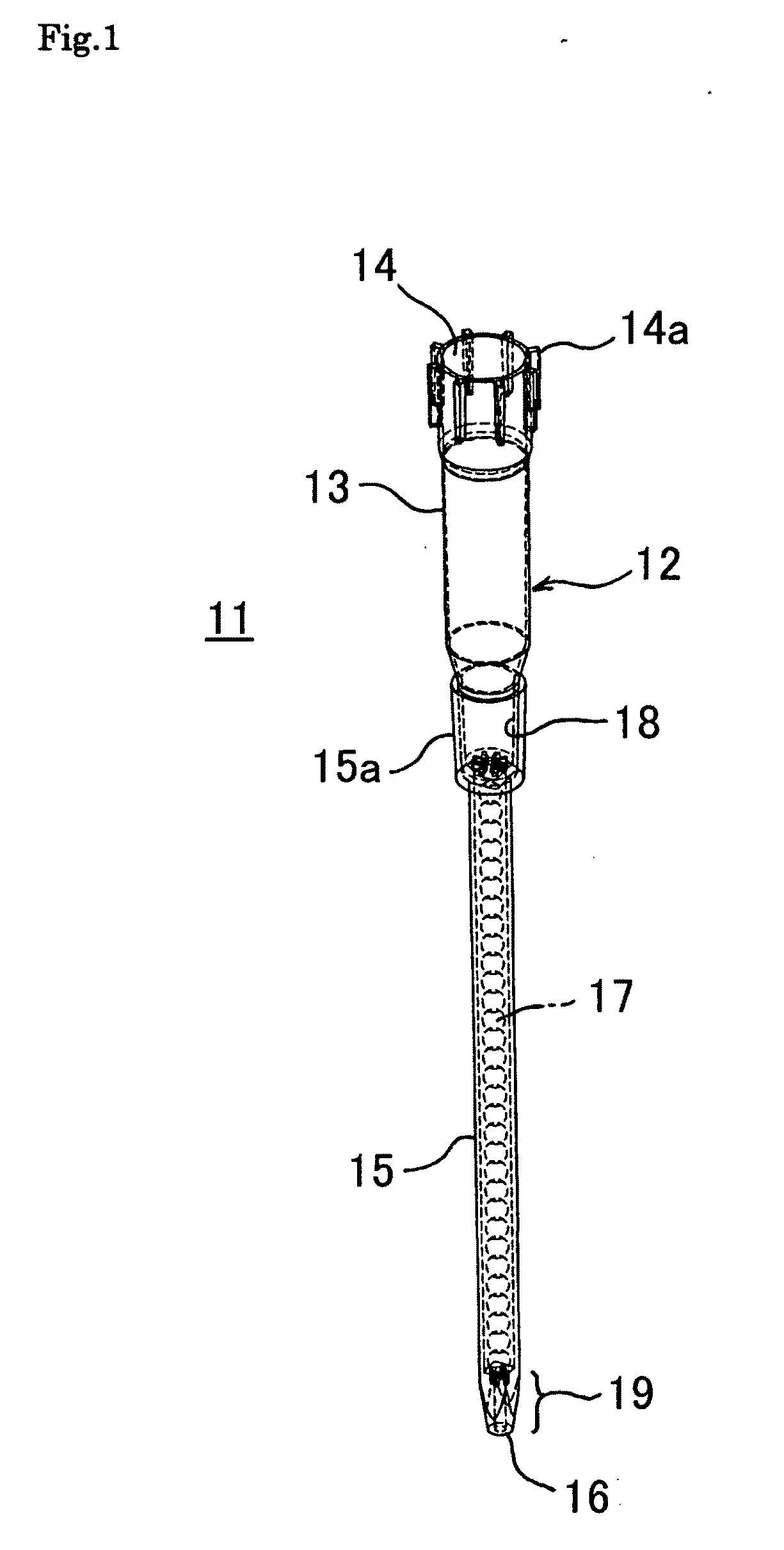
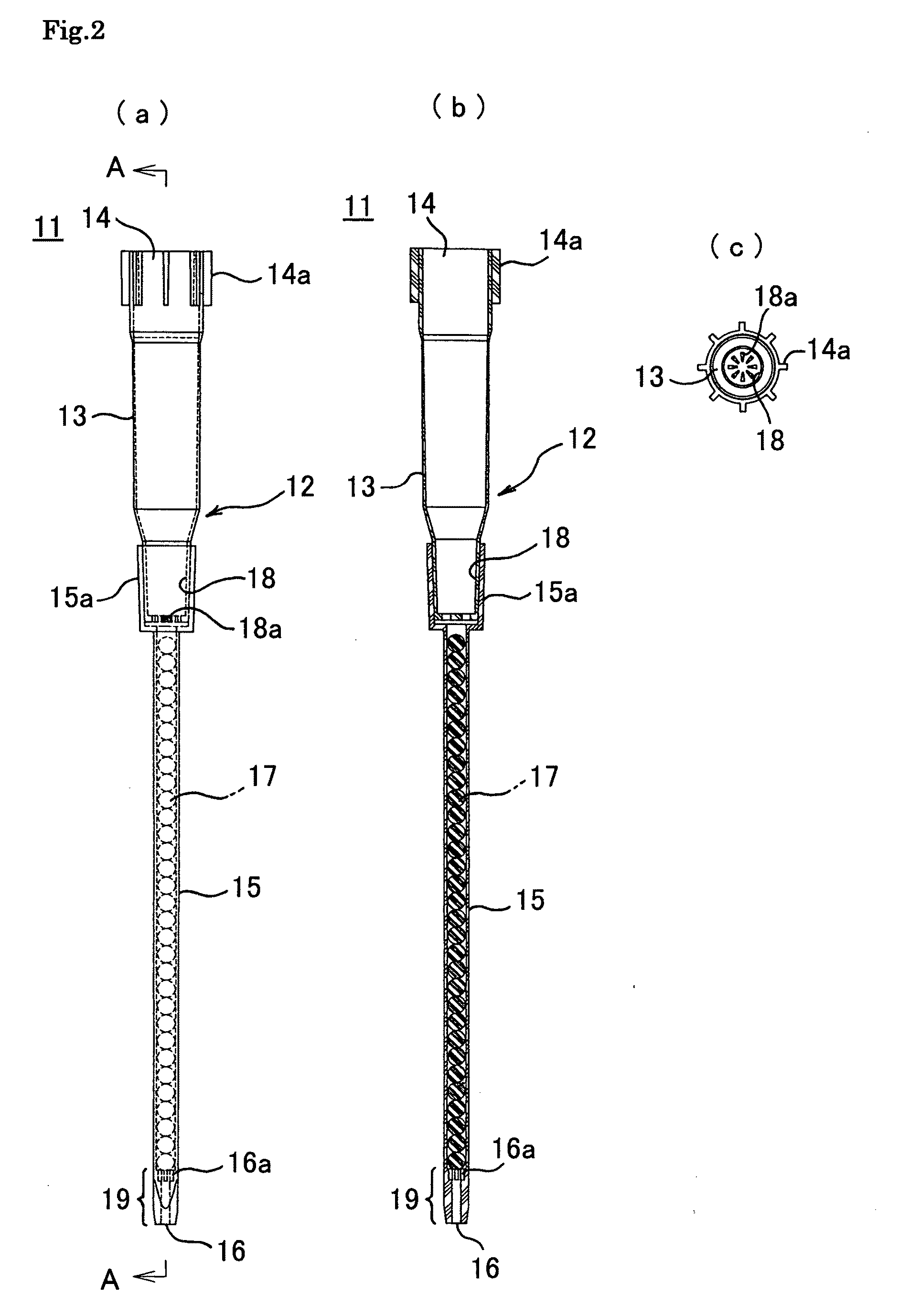
[0150]FIG. 1 shows a perspective view of a various-substance holder 11 according to the present invention. The various-substance holder 11 has a tip-like container 12 which is translucent and which serves as a carrier holding portion; the tip-like container has a thick tube 13 as a storage portion that can store a liquid and a capillary 15 formed to be thinner than the thick tube 13. The thick tube 13 has an installing opening 14 formed at an upper end thereof and which is to be installed around a nozzle (not shown) used to suck and discharge gas. The capillary 15 has a mouth portion 16 formed at a leading end thereof and through which a fluid is allowed to flow in and out by sucking and discharging the gas.

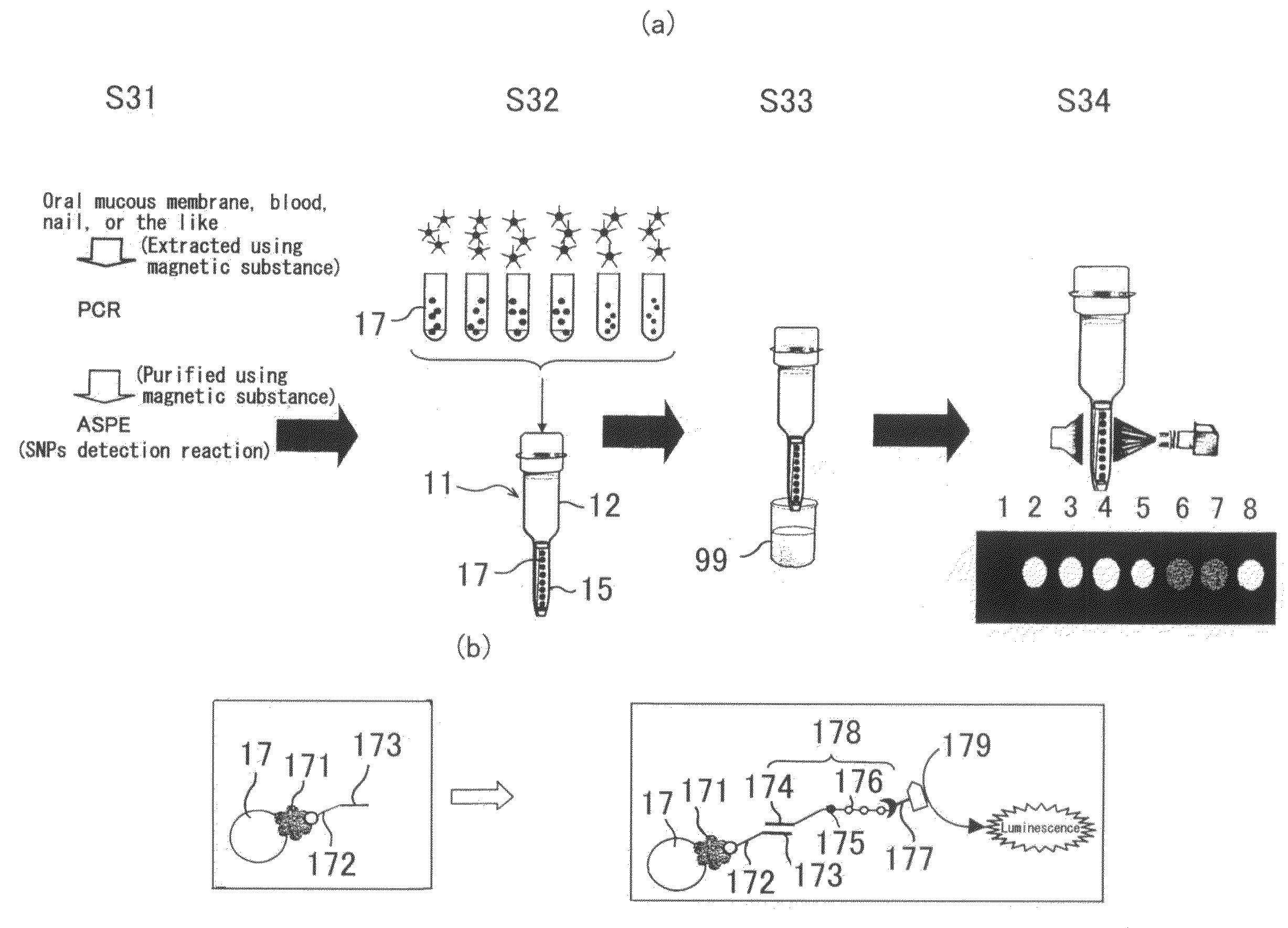
[0151]A plurality of (in this case, 31) mutually identifiably labeled particles 17 of the same shape (for example, sphere) and the same size are held in the capillary 15 in a line along the axial direction of the capillary 15 in a substantially stationary state such that the part...

third embodiment

[0163]FIG. 4(a) shows a schematic sectional view of the various-substance holder 30 according to the present invention. The various-substance holder 30 has a tip-like container 31 as the carrier holding portion and the particles 17 held in the tip-like container 31 and to which a plurality of (in this example, five; the number of the particles 17 is smaller than that in an actual case so that the figures are easier to see) the substances are or can be immobilized.

[0164]The tip-like container 31 has a thick tube 32 as the storage portion and a capillary 34 formed to be thinner than the thick tube 32. The tip-like container 31 is translucent. The thick tube 32 has an installing opening 33 formed at an upper end of the thick tube 32 and which is to be installed on a nozzle (not shown) used to suck and discharge gas. The capillary 34 has a mouth portion 35 formed at a leading end thereof and through which a fluid is allowed to flow in and out by sucking and discharging the gas. Each of ...

fourth embodiment

[0169]FIG. 4(b) shows a sectional view of the various-substance holder 41 according to the present invention. The various-substance holder 41 has a tip-like container 42 as the carrier holding portion and the particles 17 held in the tip-like container 42 and to which a plurality of (in this example, five; the number of the particles 17 is smaller than that in an actual case so that the figures are easier to see) the substances are or can be immobilized.

[0170]The tip-like container 42 has a thick tube 43 as the storage portion and a capillary 45 formed to be thinner than the thick tube 43 and removably provided on the thick tube 43. The tip-like container 42 is translucent. The thick tube 43 has an installing opening 44 formed at an upper end of the thick tube 43 and which is to be installed on a nozzle (not shown) used to suck and discharge gas. The capillary 45 has a mouth portion 46 formed at a leading end thereof and through which a fluid is allowed to flow in and out by sucking...


PUM

PropertyMeasurementUnit
Volumeaaaaaaaaaa
Temperatureaaaaaaaaaa
Concentrationaaaaaaaaaa

Abstract

An object of the present invention is to provide a various-substance holder, a various-substance holder treating apparatus, and a various-substance holder treating method which enable the mutual identification of a plurality of particulate carriers to which various substances are or can be immobilized without the need to arrange the particulate carriers at predetermined positions or in a predetermined order, eliminating the need for time and effort to arrange the various substance at predetermined positions or in a predetermined order to allow treatments to be quickly and easily achieved. The various-substance holder according to the present invention has a plurality of particulate carriers or plural sets of particulate carriers to which plural types of chemical substances are or can be immobilized and a carrier holding portion holding the plurality of particulate carriers or the plural sets of particulate carriers in a substantially stationary state such that the plurality of particulate carriers or the plural sets of particulate carriers can be externally measured. The various-substance holder is configured so that each of the plurality of particulate carriers or at least one of the particulate carriers belonging to the plural sets of the particulate carriers are labeled according to types of the chemical substances or for each of the particulate carriers or each set of the particulate carriers so as to be mutually identifiable before the particulate carriers are introduced and held in the carrier holding portion.

Description

TECHNICAL FIELD[0001]The present invention relates to a various-substance holder, a various-substance holder treating apparatus, and a various-substance holder treating method.BACKGROUND ART[0002]To be subjected to a series of reaction treatments using a large number of reagents and substances, a target substance to be checked is conventionally bonded to micro carriers such as beads before being accommodated in a test tube. Various reagents are subsequently poured into the test tube. The carriers are separated from the substance using a certain method and are then moved to another container. Another reagent or the like is further poured into the test tube, or the test tube is heated. For example, if the carriers are a magnetic substance, a magnetic field is used to attract the carriers to an inner wall of the test tube for separation.[0003]In a treatment of checking a target substance using a planar carrier such as a prepared slide to which for example, various oligonucleotides are ...

Claims


Application Information

Patent Timeline
IPC IPC(8): G01N35/00G01N37/00G01N35/10B05D3/00
CPCB01J2219/00292Y10T436/11B01J2219/00373B01J2219/005B01J2219/0052B01J2219/00545B01J2219/00576B01J2219/00596B01L3/0275B01L3/502B01L2200/0647B01L2300/0636B01L2300/0838B01L2300/1827G01N33/54313G01N35/10G01N2035/00574G01N2035/1055C12Q1/6804G01N30/6047G01N30/6073G01N30/6052B01J2219/00364G01N33/53G01N33/543G01N37/00G01N2035/00564
Inventor TAJIMA, HIDEJI
Owner UNIVERSAL BIO RESEARCH CO LTD
Why Eureka
Try Eureka