Method and apparatus for combusting fuel within a gas turbine engine

a gas turbine engine and combustion system technology, applied in combustion control, turbine/propulsion engine ignition, lighting and heating apparatus, etc., can solve the problems of diffusion fuel flame blowing out, premature wear of combustor hardware surrounding the flame, and increase in temperatur

Active Publication Date: 2009-09-10
GENERAL ELECTRIC CO
View PDF23 Cites 60 Cited by
  • Summary
  • Abstract
  • Description
  • Claims
  • Application Information

AI Technical Summary

Problems solved by technology

The increased concentration of diffusion fuel may undesirably increase a fuel rich fuel/air ratio downstream from the fuel injection nozzles such that the fuel/air ratio is increases beyond the upper design limit.
Such a fuel rich environment may exceed a rich blow out (RBO) boundary causing the diffusion fuel flame to blow out.
A turbine start-up that injects premixed fuel before the turbine reaches full speed may be referred to, for example, as a “lean-lean start.” However, because the premix fuel flame is more unstable than diffusion fuel flames, to facilitate stabi

Method used


Image

  • Method and apparatus for combusting fuel within a gas turbine engine
  • Method and apparatus for combusting fuel within a gas turbine engine
  • Method and apparatus for combusting fuel within a gas turbine engine

Examples


Embodiment Construction

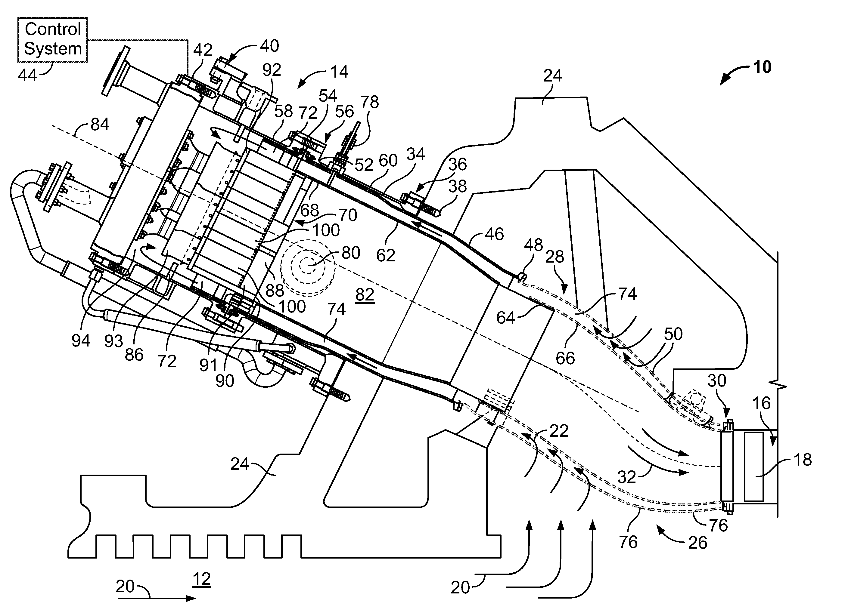
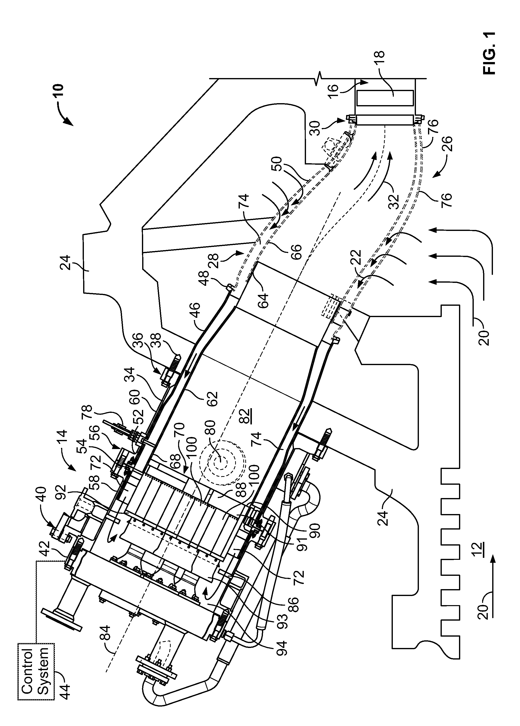
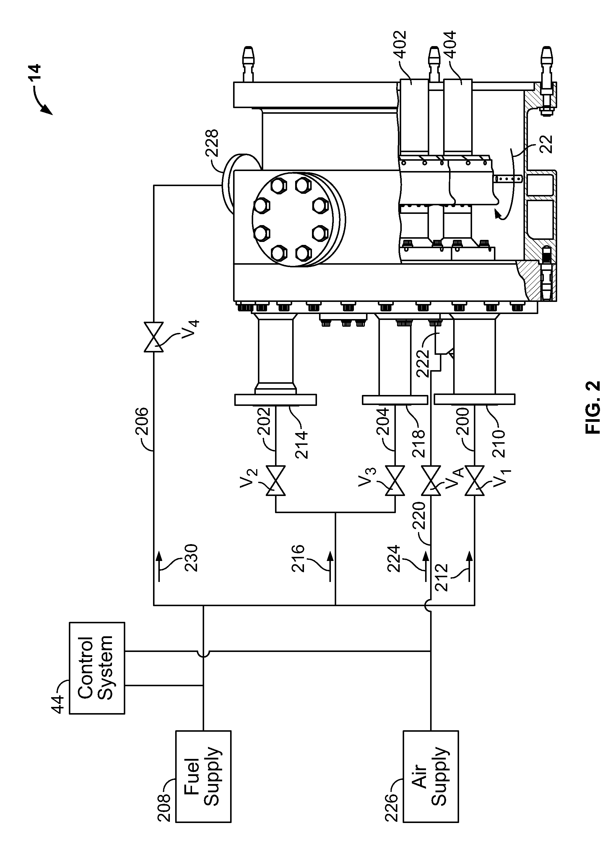
[0016]FIG. 1 is partial cross-sectional view of an exemplary gas turbine engine 10 that includes a plurality of fuel nozzle assemblies 400. FIG. 2 is a schematic side view of a portion of gas turbine engine 10. FIG. 3 is front view of the portion of gas turbine engine 10 shown in FIG. 2.

[0017]Gas turbine engine 10 includes a compressor 12, a combustor 14, and a turbine 16. Only a first stage nozzle 18 of turbine 16 is shown in FIG. 1. In the exemplary embodiment, turbine 16 is drivingly coupled to compressor 12 with rotors (not shown) that are connected by a single common shaft (not shown). Compressor 12 pressurizes inlet air 20 which is then channeled to combustor 14 where it cools combustor 14 and provides air to the combustion process. More specifically, air 22 channeled to combustor flows in a direction generally opposite to the flow of air through engine 10. In the exemplary embodiment, gas turbine engine 10 includes a plurality of combustors 14 oriented circumferentially about...


PUM

PropertyMeasurementUnit
Fractionaaaaaaaaaa
Fractionaaaaaaaaaa
Angleaaaaaaaaaa

Abstract

A method for operating a gas turbine engine including a combustor assembly is provided. The method includes channeling a first fluid through a first nozzle into the combustor assembly, igniting the first fluid within the combustor assembly downstream from the first nozzle, channeling a second fluid through a second nozzle into the combustion assembly when the gas turbine engine attains a speed of greater than 85% of rated speed, igniting the second fluid within the combustor assembly downstream from the second nozzle, terminating a flow of the first fluid through the first nozzle, and channeling the second fluid to the first nozzle.

Description

BACKGROUND OF THE INVENTION[0001]This invention relates generally to a gas turbine engine, and, more specifically, to a combustion system for a gas turbine engine.[0002]In at least some known gas turbine engine combustion systems, to facilitate reducing the possibility of lean blow-out, or a blow out caused when the environment has a low fuel to air ratio, diffusion fuel is used to start turbine operation. Depending on the turbine, diffusion fuel injected through fuel nozzles may become concentrated downstream from the fuel injection nozzles. The increased concentration of diffusion fuel may undesirably increase a fuel rich fuel / air ratio downstream from the fuel injection nozzles such that the fuel / air ratio is increases beyond the upper design limit. Such a fuel rich environment may exceed a rich blow out (RBO) boundary causing the diffusion fuel flame to blow out. More specifically, most known rich blow outs occur at about 80% of turbine speed during turbine start up.[0003]Some k...

Claims


Application Information

Patent Timeline
IPC IPC(8): F02C7/26F02C7/22
CPCF02C7/264F02C9/263F02C9/34F23D2900/00008F23N1/022F23N2027/02Y10T29/49236F23N2037/08F23N2037/10F23N2041/20F23R3/286F23R3/343F23R3/36F23N2037/02F23N2227/02F23N2237/02F23N2237/08F23N2237/10F23N2241/20
Inventor ROMOSER, CAREY EDWARD
Owner GENERAL ELECTRIC CO
Why Eureka
Try Eureka