Fringe projection system and method for a probe suitable for phase-shift analysis

a projection system and phase-shift analysis technology, applied in the field of borescopes/endoscopes, can solve the problems of time-consuming, difficult to directly determine dimensional measurements, and provide information, and achieve the effect of generating a full 3d surface map and reducing the cost of production

Active Publication Date: 2009-09-10
GE INSPECTION TECH LP
View PDF21 Cites 87 Cited by
  • Summary
  • Abstract
  • Description
  • Claims
  • Application Information

AI Technical Summary

Problems solved by technology

This leads to difficulties in directly determining dimensional measurements, especially in three spatial dimensions.
Stereo methods can be used to create a 3D view, but can only provide information where two points on the image can be correlated.
This can be problematic when little surface detail exists.
The correlation process can also require significant processing, so producing a full 3D surface map can be time consuming.
However, the areas between the dots are left to be interpolated, so any surface variations between them are lost.
Finally, a single line profile provides useful information along that single profile, but proper positioning of the single line on the object of interest can be difficult, and measurements that require non co-linear points, such as point to line or area

Method used


Image

  • Fringe projection system and method for a probe suitable for phase-shift analysis
  • Fringe projection system and method for a probe suitable for phase-shift analysis
  • Fringe projection system and method for a probe suitable for phase-shift analysis

Examples


Embodiment Construction

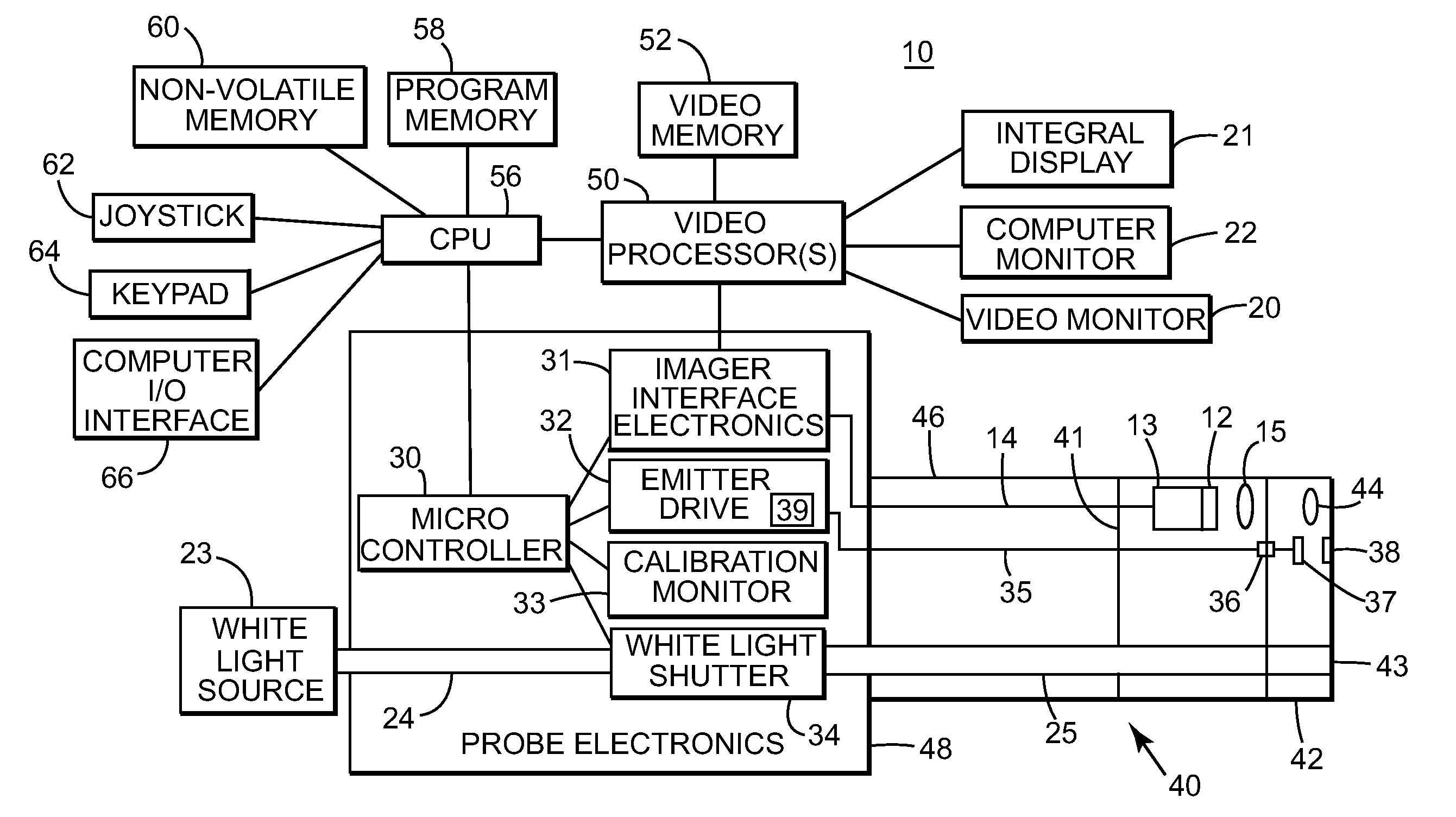
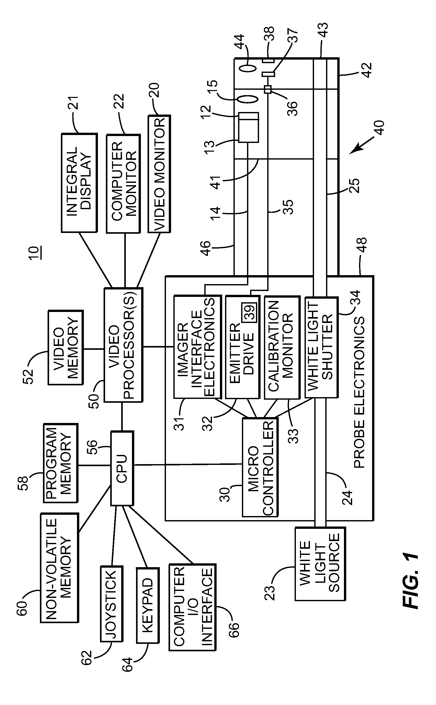
[0026]Illustrated in FIG. 1, a borescope / endoscope system or probe 10 according to an embodiment of the invention is shown. An insertion tube 40 comprises elongated portion 46 and detachable distal tip 42. Elongated portion 46 comprises a main long, flexible portion, a bending neck, and a camera head. Delineation line 41 shows where the camera head starts on elongated portion 46. The camera head of elongated portion 46 typically includes at least imager 12, electronics 13, and probe optics 15. Detachable distal tip 42 typically attaches to the camera head of elongated portion 46, mentioned above. Detachable distal tip 42 contains viewing optics 44 which are used in combination with probe optics 15 to guide and focus light received from the surface or object (not shown) onto imager 12. The viewing optics 44 may optionally include relay optics such as a lens or fiber optic system to remote the camera head away from the distal tip.

[0027]Imager 12 may comprise, for example, a two-dimens...


PUM


Abstract

A probe includes an insertion tube and a plurality of light emitters disposed on the distal end of the insertion tube. The probe further includes at least one intensity modulating element through which light from the plurality of light emitters is passed to project a plurality of fringe sets onto a surface. Each of the plurality of fringe sets intern have a structured-light pattern that is projected when one emitter group of at least one of the plurality of light emitters is emitting. The probe further includes an imager for obtaining at least one image of the surface and a processing unit that is configured to perform phase-shift analysis on the at least one image. A method for projecting a plurality of fringe sets suitable for phase-shift analysis on a surface using a probe is also presented.

Description

BACKGROUND OF THE INVENTION[0001]1. Field of the Invention[0002]The subject matter described herein relates generally to borescopes and endoscopes, and more particularly, to a borescope / endoscope which provides 3D surface mapping and dimensional measurement.[0003]2. Related Art[0004]Borescopes and endoscopes are typically used for inspection inside a remote cavity. Most borescopes / endoscopes, referred to herein as probes, employ an external light source coupled to fiber optic bundles in the probe to provide illumination of a remote object or surface at the distal end. When the object is illuminated, an internal image is formed by a lens system on an image sensor, and the image is relayed to a connected display, such as a video screen. The image sensor may be located at the proximal end of the probe, as with an optical rigid borescope or fiberscope, or at the distal end as with a video borescope or endoscope. Such systems are often used to inspect in inaccessible locations for damage...

Claims


Application Information

Patent Timeline
IPC IPC(8): G01N21/55
CPCG01B11/2527
Inventor BENDALL, CLARK ALEXANDERSONG, GUIJUTAO, LIHARDING, KEVIN GEORGEKARPEN, THOMAS
Owner GE INSPECTION TECH LP
Why Eureka
Try Eureka