Optical frequency synthesizer and optical frequency synthesizing method using femtosecond laser optical injection locking

a technology of optical injection locking and optical frequency synthesizer, which is applied in the direction of semiconductor lasers, laser details, electrical apparatus, etc., can solve the problems of difficult to select only a single mode and form a single-mode laser having a desired frequency, and the optical frequency synthesizers that have been developed to date are very complicated

Active Publication Date: 2009-09-10
KOREA RES INST OF STANDARDS & SCI
View PDF1 Cites 15 Cited by
  • Summary
  • Abstract
  • Description
  • Claims
  • Application Information

AI Technical Summary

Benefits of technology

[0007]Accordingly, the present invention has been made keeping in mind the above problems occurring in the prior art, and an object of the present invention is to provide an optical frequency synthesizer and an optical frequency synthesizing method using femtosecond laser optical injection locking, which inject a femtosecond laser optical frequency comb into a diode laser, thus obtaining single-mode laser light, phase-locked to only a single mode in the optical frequency comb, and which change the optical frequency and interval, that is, the repetition rate, of a femtosecond laser, together with the frequency of a semiconductor laser, thus enabling optical frequencies to be scanned while realizing a single desired optical frequency.
[0015]Further, the present invention provides an optical frequency synthesizing method using femtosecond laser optical injection locking, wherein a mode-locked femtosecond laser is used as a master laser, and a diode laser, which oscillates in a single mode, is used as a slave laser, so that the laser light of the master laser is injected into the slave laser, and single mode laser light phase-locked only to a single mode of a frequency comb of the femtosecond laser, which is a master laser, is acquired, wherein an interval (repetition rate) of the optical frequency comb of the femtosecond laser is changed together with frequency of the diode laser, thus obtaining laser light enabling scanning of optical frequencies.
[0016]The frequency of optical injection-locked laser light emitted from the femtosecond laser, which is a master laser, is adjusted to a desired optical frequency by changing the frequency of the microwave frequency synthesizer. In this case, the frequency of the diode laser, which is a slave laser, is changed by changing the current that is supplied to the diode laser, thus consequently obtaining laser light having a desired frequency while maintaining an optical injection-locked state. In this case, the frequency of the femtosecond laser is changed by changing the interval (repetition rate) of the optical frequency comb of the femtosecond laser, thus enabling scanning to be performed.
[0018]Accordingly, the optical frequency synthesizer and optical frequency synthesizing method using femtosecond laser optical injection locking of the present invention is advantageous in that laser light, obtained from a mode-locked femtosecond laser, is injected into a diode laser, thus obtaining single-mode laser light, phase-locked only to a single mode in the optical frequency comb of a mode-locked femtosecond laser, and in that the optical frequency and interval, that is, the repetition rate, of laser light emitted from the femtosecond laser is changed together with the frequency of a semiconductor laser, thus enabling optical frequencies to be scanned.

Problems solved by technology

However, such technology is disadvantageous in that the frequency of a femtosecond laser comb has been defined, but it is still difficult to select only a single mode and form a single-mode laser having a desired frequency, or to scan the frequency, and in that the optical frequency synthesizers that have been developed to date are very complicated.

Method used


Image

  • Optical frequency synthesizer and optical frequency synthesizing method using femtosecond laser optical injection locking
  • Optical frequency synthesizer and optical frequency synthesizing method using femtosecond laser optical injection locking
  • Optical frequency synthesizer and optical frequency synthesizing method using femtosecond laser optical injection locking

Examples


Embodiment Construction

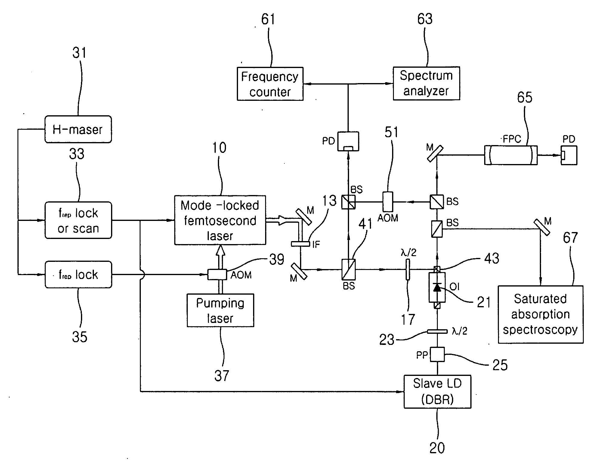
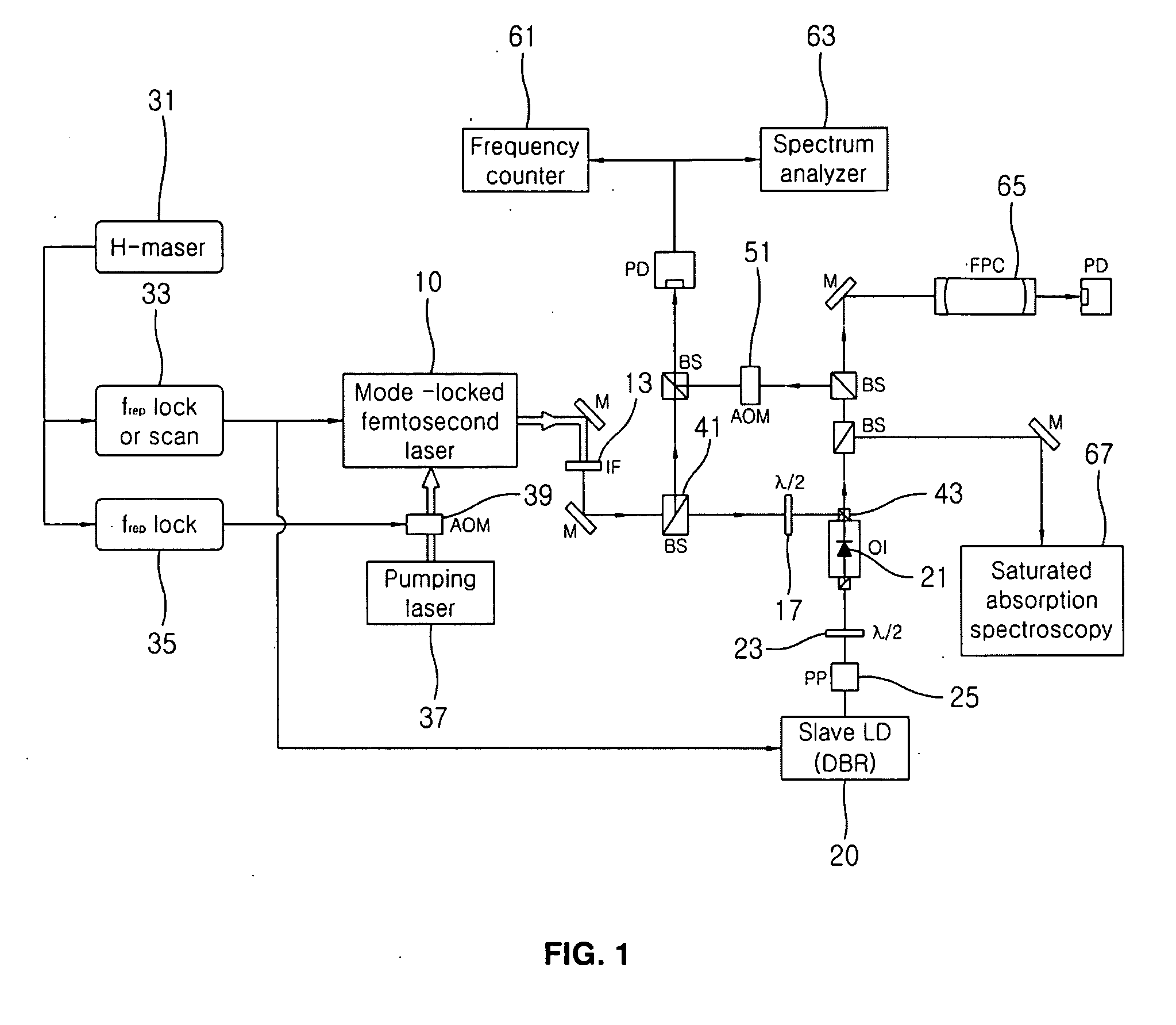
[0026]The embodiment of FIG. 7 illustrates the connection of an fceo adjustment microwave frequency synthesizer 135, connected to a hydrogen maser 131, and a frep adjustment microwave frequency synthesizer 133, through a detailed example.

[0027]The construction in which an Acousto-Optic Modulator (AOM) 139, a pump laser 137, the fceo adjustment microwave frequency synthesizer 135, and the frep adjustment microwave frequency synthesizer 133 are arranged near the femtosecond laser and the diode laser, is depicted. The femtosecond laser 110 is connected to the pump laser 137 through the AOM 139. The femtosecond laser 110 is synchronized with the frep adjustment microwave frequency synthesizer 133 to adjust the repetition rate of the femtosecond laser by adjusting the output signal frequency frep of the frep adjustment microwave frequency synthesizer 133.

[0028]Laser light emitted from the femtosecond laser 110 is split by a beam splitter 141, so that, for example, 5 to 15% of the laser l...


PUM


Abstract

The present invention relates to an optical frequency synthesizer and an optical frequency synthesizing method using femtosecond laser optical injection locking, which inject a femtosecond laser optical frequency comb into a diode laser, thus obtaining single-mode laser light, phase-locked to only a single mode in the optical frequency comb, and which change the optical frequency and interval, that is, the repetition rate, of a femtosecond laser, together with the frequency of a semiconductor laser, thus scanning optical frequencies while realizing a single desired optical frequency. The optical frequency synthesizer using femtosecond laser optical injection locking, includes a mode-locked femtosecond laser (110), which is a master laser, and a diode laser (120), which is a slave laser and into which laser light emitted from the femtosecond laser is injected.

Description

REFERENCE TO RELATED APPLICATIONS[0001]This a continuation of pending International Patent Application PCT / KR2007 / 004848 filed on Oct. 4, 2007, which designates the United States and claims priority of Korean Patent Application No. 10-2006-0098825 filed on Oct. 11, 2006, the entire contents of which are incorporated herein by reference.FIELD OF THE INVENTION[0002]The present invention relates to an optical frequency synthesizer and optical frequency synthesizing method using femtosecond laser optical injection locking.BACKGROUND OF THE INVENTION[0003]Technology for the absolute measurement of optical frequency is essentially required in the age of optical Internet-based information communication. When the wavelength or the frequency, of light used in optical communication can be precisely measured, the wavelength can be finely split to a desired degree. This enables transmission based on Dense Wavelength Division Multiplexing (DWDM), in which multiple wavelengths are divided and sep...

Claims


Application Information

Patent Timeline
Patent Type & Authority Applications(United States)
IPC IPC(8): H01S3/098H01S3/10
CPCH01S3/10092H01S3/1106H01S5/4006H01S3/1643H01S3/1603
Inventor PARK, SANG EONMOON, HAN SEBKIM, EOK BONGPARK, CHANG YOUNGKWON, TAEG YONG
Owner KOREA RES INST OF STANDARDS & SCI
Why Eureka
Try Eureka