Micro-fiber probe loss modulation-based polymer bottle micro-cavity single-mode laser component

A technology of laser components and polymers, applied in laser parts, lasers, electrical components, etc., can solve problems such as large scattering loss, and achieve the effect of simple and compact structure

Active Publication Date: 2017-12-08
UNIV OF SHANGHAI FOR SCI & TECH
View PDF2 Cites 11 Cited by
  • Summary
  • Abstract
  • Description
  • Claims
  • Application Information

AI Technical Summary

Problems solved by technology

Usually, due to the diameter mismatch between the fiber probe and the resonator, although a fraction of the input power can be ...

Method used


Image

  • Micro-fiber probe loss modulation-based polymer bottle micro-cavity single-mode laser component
  • Micro-fiber probe loss modulation-based polymer bottle micro-cavity single-mode laser component
  • Micro-fiber probe loss modulation-based polymer bottle micro-cavity single-mode laser component

Examples


preparation example Construction

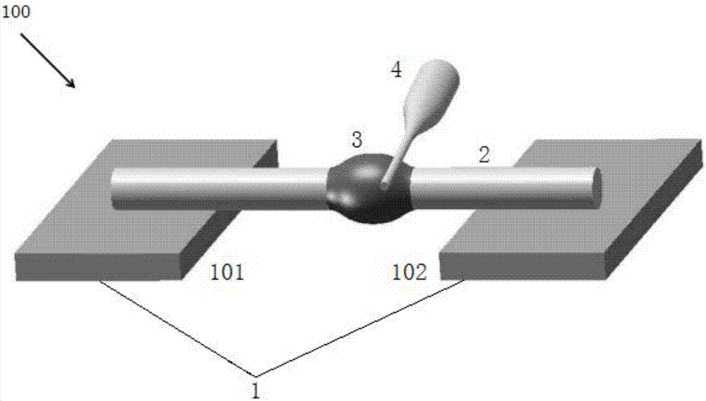
[0038] The preparation method of the polymer bottle microcavity single-mode laser element 100 based on the micro-fiber probe loss modulation of the present embodiment includes the following steps:

[0039] Step 1, using a carbon dioxide laser as a heat source, drawing an ordinary single-mode optical fiber by high temperature stretching method, and preparing a micro optical fiber 2 and a pump optical fiber probe 4;

[0040] Step 2, placing the two ends of the micro-optical fiber 2 on the first slide 101 and the second slide 102, and the middle section is suspended;

[0041] Step 3, dissolving the laser gain substance in a polymer organic solvent and mixing it with a high-viscosity resin and a curing agent, and then oscillating evenly on a circular oscillating shaker to obtain a resin solution;

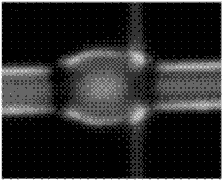
[0042] Step 4, immersing the pump fiber optic probe 4 in the resin solution prepared in step 4 and quickly extracting to obtain micro-droplets;

[0043] Step 5, under the optical micro...

Embodiment 1

[0050] The preparation method of the single-mode laser element is as follows:

[0051] Step 1, using a carbon dioxide laser as a heat source, drawing a common single-mode optical fiber by a high-temperature drawing method, and preparing a micro-fiber 2 with a diameter of 3.2 μm and a pumping optical fiber probe 4 with a tip diameter of 1.1 μm;

[0052] Step 2, placing the two ends of the micro-optical fiber 2 on the first slide 101 and the second slide 102 with an interval of 2000 μm, and the middle section is suspended;

[0053] Step 3, dissolve the R6G laser dye in chloroform and mix it with high-viscosity epoxy resin and curing agent, and then oscillate evenly on a circular oscillating shaker to prepare an epoxy resin solution uniformly doped with R6G laser dye. R6G laser dye is in The mass concentration in epoxy resin solution is 2.5%, and the volume ratio of chloroform and high viscosity epoxy resin is 1:10;

[0054] Step 4, immersing the pump fiber optic probe 4 with a ...


PUM

PropertyMeasurementUnit
Diameteraaaaaaaaaa
Diameteraaaaaaaaaa
Diameteraaaaaaaaaa

Abstract

The invention discloses a micro-fiber probe loss modulation-based polymer bottle micro-cavity single-mode laser component. The single-mode laser component comprises a glass slide, a micro-fiber, a polymer bottle micro-cavity and a pumping fiber probe, wherein the glass slide comprises a first glass slide and a second glass slide which are arranged in parallel, two ends of the micro-fiber are respectively arranged on the first glass slide and the second glass slide, the polymer bottle micro-cavity sleeves a middle part of the micro-fiber, the pumping fiber probe is arranged on the polymer bottle micro-cavity and is coupled to the polymer bottle micro-cavity, the polymer bottle micro-cavity is formed by curing a resin solution, and the constituent of the resin solution comprises a laser gain substance, a macromolecule organic solvent, high-viscosity resin and a curing agent. The single-mode laser component is implemented by changing a coupling position of the pumping fiber probe on an axial direction of the polymer bottle micro-cavity; and since great scattering loss is caused by photoluminescence of the pumping light probe at the coupling position, a high-order laser mode is pressured, a base mode in a symmetric center of the cavity is only simulated, so that the output of single-mode laser is achieved.

Description

technical field [0001] The invention relates to a micro-nano optical device, in particular to a polymer bottle microcavity single-mode laser element based on micro-fiber probe loss modulation. Background technique [0002] Whispering gallery mode (WGM) optical microcavities circulate light along equatorial trajectories close to the cavity surface for a long time before being scattered or absorbed, and have attractive advantages such as long photon lifetime, strong optical field confinement, and in-plane emission, It is used in many fields including laser, sensing, optical communication and so on. So far, WGMs have been realized with many cavities with different structures, such as microspheres, microrings, microdroplets, microdisks, microring cores, and microfibers, etc. The output of WGM lasers is usually multimode due to the lack of mode selection strategy. As far as we know, a straightforward way to achieve single-mode lasing is to reduce the size of the microcavity, bu...

Claims


Application Information

Patent Timeline
IPC IPC(8): H01S3/08
CPCH01S3/08018H01S3/08031
Inventor 谷付星谢富名
Owner UNIV OF SHANGHAI FOR SCI & TECH
Why Eureka
Try Eureka