Porous gas heating device for a vapor deposition system

Inactive Publication Date: 2009-09-10
TOKYO ELECTRON LTD
View PDF50 Cites 24 Cited by
  • Summary
  • Abstract
  • Description
  • Claims
  • Application Information

AI Technical Summary

Benefits of technology

[0011]The invention further relates to a method and system for depositing a thin film using pyrolytic CVD, wherein a gas distribution device comprising one or more porous gas distribution elements is utilized to pyrolize a film forming composition.
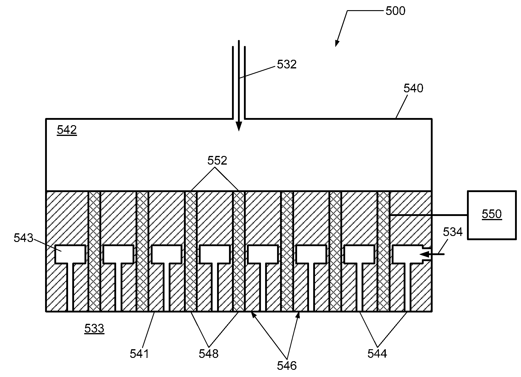
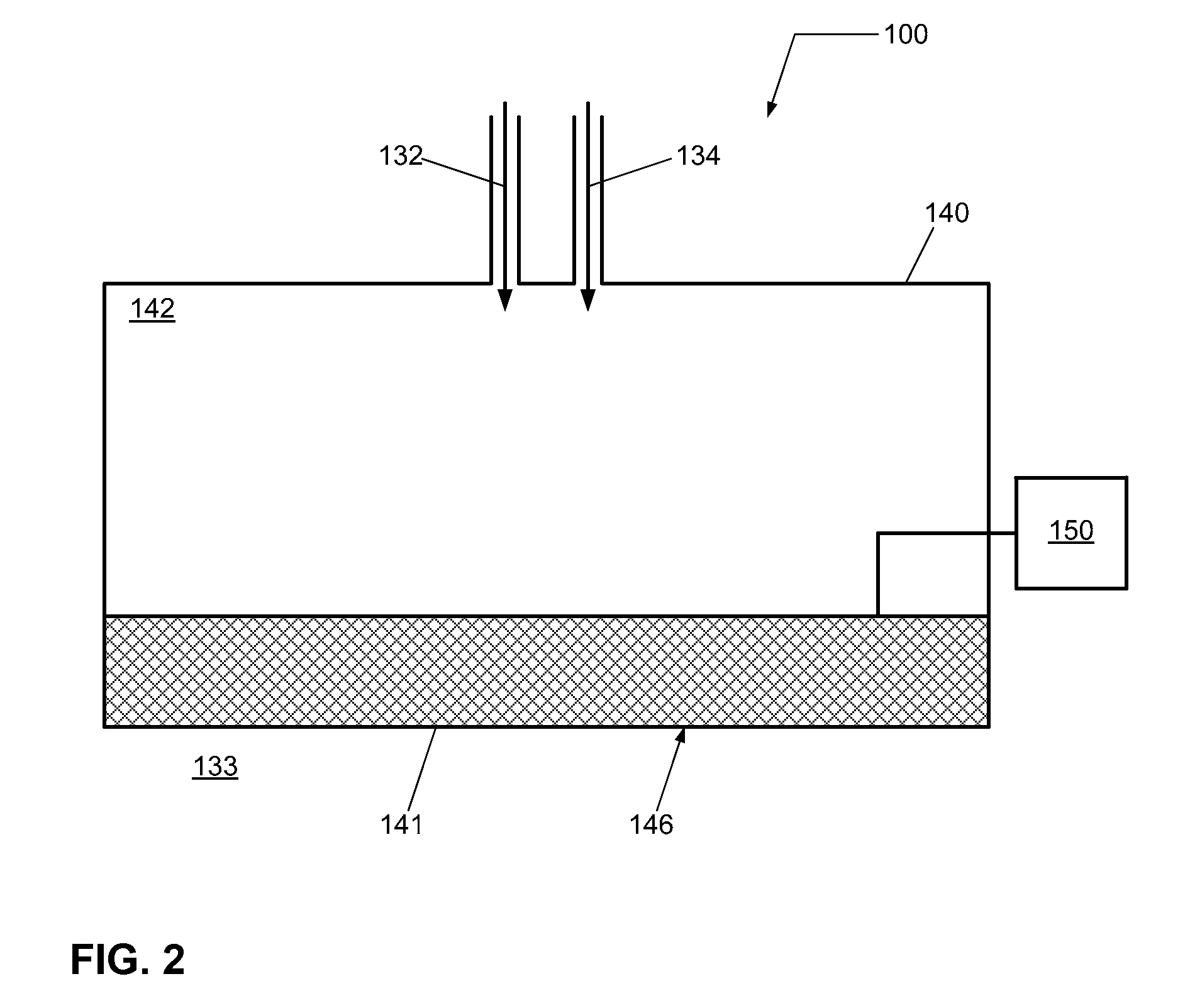
[0012]According to one embodiment, a gas distribution device configured to be coupled to a processing system is described. The gas distribution device is configured to heat a process gas, such as one or more constituents of a film forming composition. For example, the system may be used to deposit a thin film on a substrate using a vapor deposition process. The gas distribution device comprises one or more porous gas distribution elements configured to be heated and pyrolize a process gas flowing through the one or more porous gas distribution elements. For example, the one or more porous gas distribution elements may comprise an open-celled foam.
[0013]According to another embodiment, a gas distribution device configured to be coupled to a processing system is described. The gas distribution device comprises a temperature control element; and one or more porous gas distribution elements coupled

Problems solved by technology

In addition, plasma excitation may activate film-forming chemical reactions that are not energetically or kinetically favored in thermal CVD.
However, hot-filament CVD

Method used


Image

  • Porous gas heating device for a vapor deposition system
  • Porous gas heating device for a vapor deposition system
  • Porous gas heating device for a vapor deposition system

Examples


Embodiment Construction

[0029]In the following description, in order to facilitate a thorough understanding and for purposes of explanation and not limitation, specific details are set forth, such as a particular geometry of the deposition system and descriptions of various components.

[0030]However, one skilled in the relevant art will recognize that the various embodiments may be practiced without one or more of the specific details, or with other replacement and / or additional methods, materials, or components. In other instances, well-known structures, materials, or operations are not shown or described in detail to avoid obscuring aspects of various embodiments of the invention. Similarly, for purposes of explanation, specific numbers, materials, and configurations are set forth in order to provide a thorough understanding of the invention. Nevertheless, the invention may be practiced without specific details. Furthermore, it is understood that the various embodiments shown in the figures are illustrati...


PUM

PropertyMeasurementUnit
Fractionaaaaaaaaaa
Fractionaaaaaaaaaa
Fractionaaaaaaaaaa

Abstract

A method and system for treating a substrate is described. For example, the method and system may be used to deposit a thin film on a substrate using a vapor deposition process. The processing system comprises a gas distribution device for controlling the temperature of a process gas, such as one or more constituents of a film forming composition. The gas distribution device comprises one or more porous gas distribution elements configured to be temperature controlled and distribute a process gas flowing through the one or more porous gas distribution elements. The gas distribution device may be configured to pyrolize the process gas.

Description

CROSS-REFERENCE TO RELATED APPLICATIONS[0001]This application is related to pending U.S. patent application Ser. No. 11 / 693,067, entitled “VAPOR DEPOSITION SYSTEM AND METHOD OF OPERATING”, Docket No. TTCA-195, filed on Mar. 29, 2007; and pending U.S. patent application Ser. No. 12 / xxx,xxx, entitled “GAS HEATING DEVICE FOR A VAPOR DEPOSITION SYSTEM”, Docket No. TTCA-216, filed on Feb. dd, 2008. The entire content of these applications is herein incorporated by reference in its entirety.BACKGROUND OF THE INVENTION[0002]1. Field of Invention[0003]The present invention relates to a method and system for substrate processing, and more particularly to a method and system for distributing a gas during substrate processing.[0004]2. Description of Related Art[0005]During material processing, such as semiconductor device manufacturing for production of integrated circuits (ICs), vapor deposition is a common technique to form thin films, as well as to form conformal thin films over and within ...

Claims


Application Information

Patent Timeline
IPC IPC(8): C23C16/455
CPCC23C16/448C23C16/4557C23C16/45563
Inventor NASMAN, RONALD
Owner TOKYO ELECTRON LTD
Why Eureka
Try Eureka