
Treatment liquid supply apparatus and substrate treatment apparatus including the same

a technology of liquid supply apparatus and substrate treatment apparatus, which is applied in the direction of chemistry apparatus and processes, cleaning processes and apparatus, and using liquids to achieve the effect of suppressing or preventing the failure of substrate treatmen

Active Publication Date: 2009-09-17
DAINIPPON SCREEN MTG CO LTD
View PDF4 Cites 51 Cited by
  • Summary
  • Abstract
  • Description
  • Claims
  • Application Information

AI Technical Summary

Benefits of technology

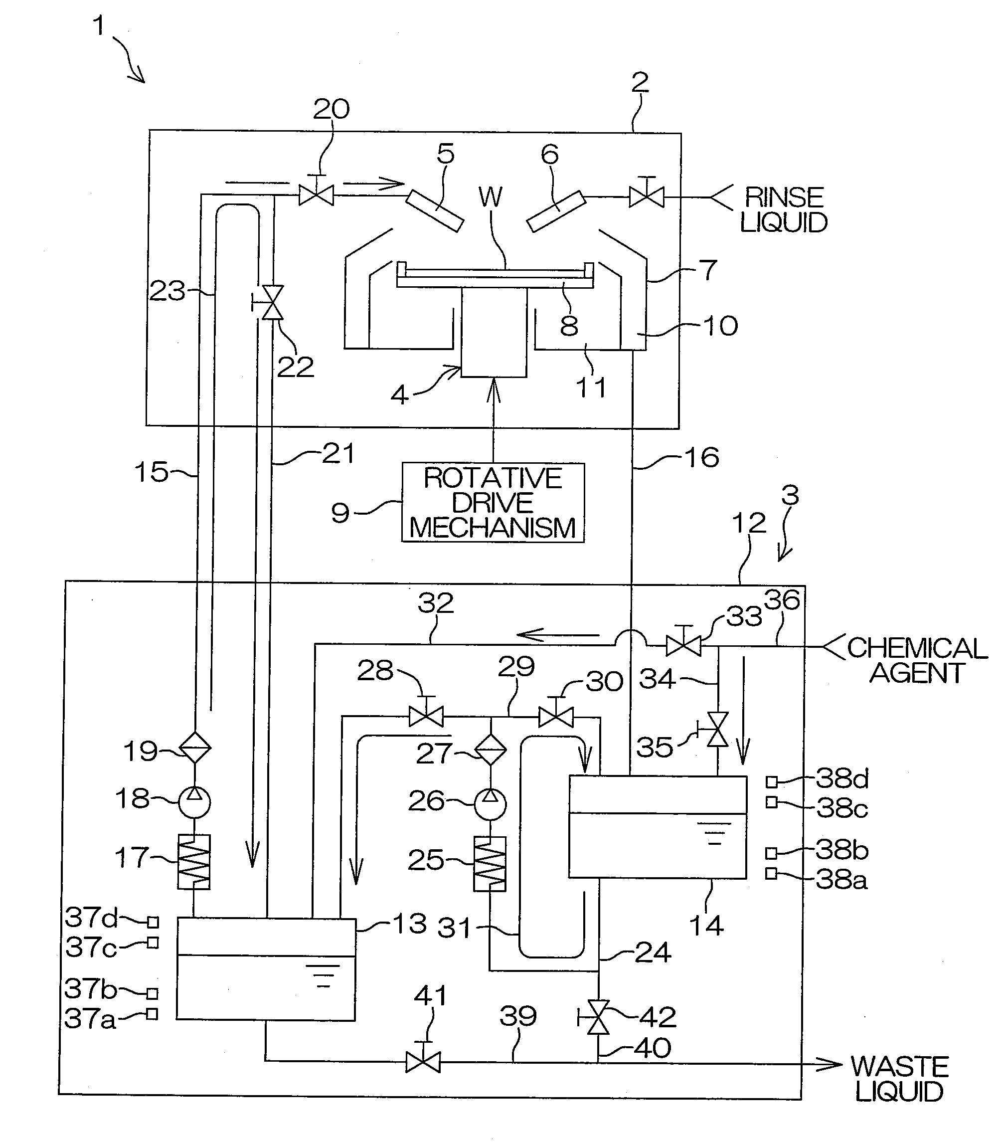
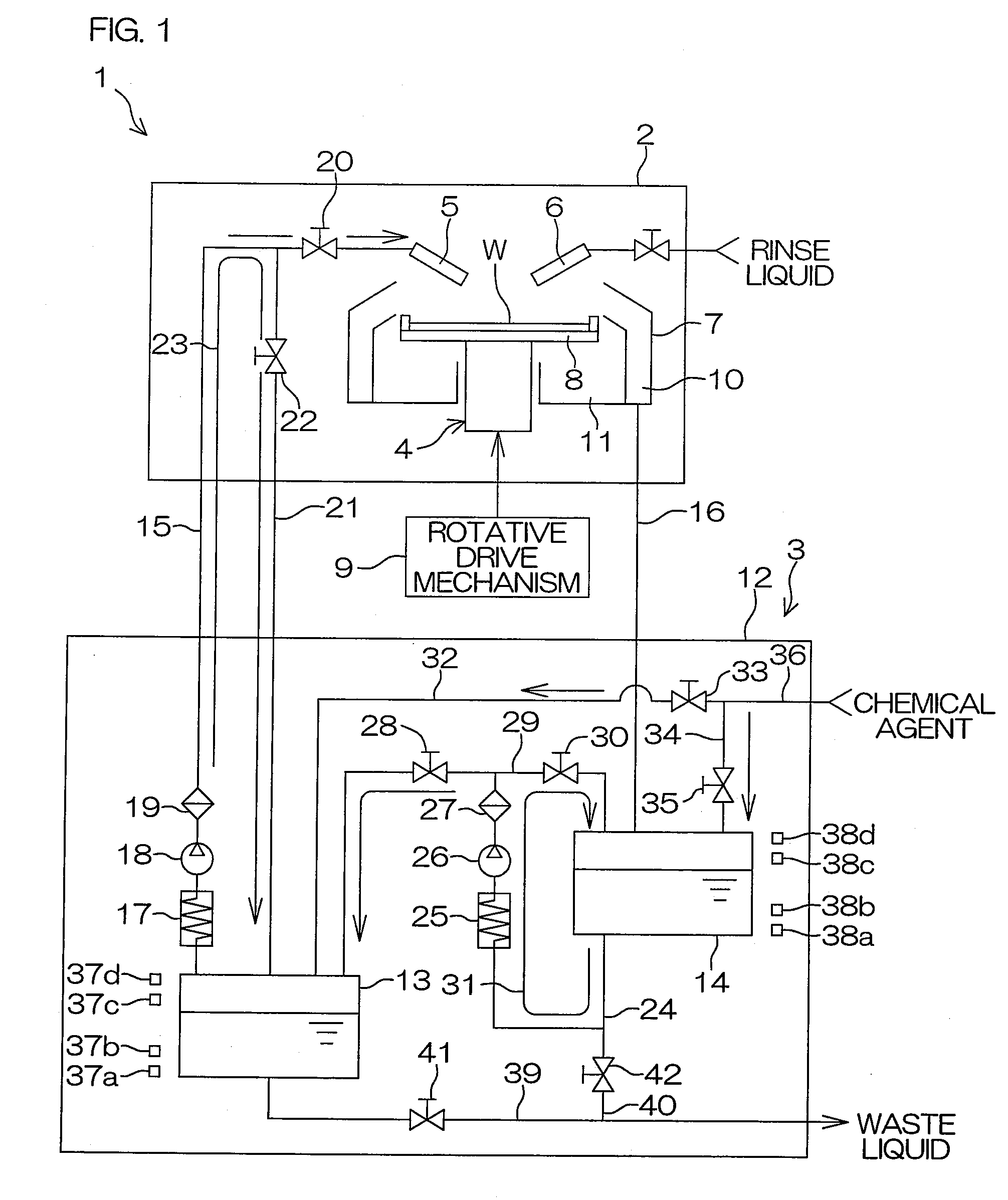
[0012]The treatment liquid recovered in the second tank is transferred to the first tank by the transfer unit with its temperature being regulated by the second temperature regulating unit. That is, the recovered treatment liquid is fed into the first tank after the temperature thereof is preliminarily regulated. This suppresses significant temperature change of the treatment liquid which may otherwise occur in the first tank due to the recovered treatment liquid. Therefore, the treatment liquid can be supplied to the object at the stable temperature.
[0013]That is, where the first temperature regulating unit is adapted to regulate the temperature of the treatment liquid stored in the first tank, the liquid temperature in the first tank is maintained at the first temperature level, so that the temperature of the treatment liquid to be supplied to the object is stabilized. Further, where the first temperature regulating unit is adapted to regulate the temperature of the treatment liquid in the treatment liquid supply pipe, the temperature of the treatment liquid can be immediately adjusted at the first temperature level in the treatment liquid supply pipe, because the temperature of the treatment liquid supplied to the treatment liquid supply pipe from the first tank is closer to the first temperature level. Thus, the temperature of the treatment liquid to be supplied to the object is stabilized.
[0014]The second temperature level at which the treatment liquid is temperature-regulated by the second temperature regulating unit is preferably equal to or substantially equal to the first temperature level at which the treatment liquid is temperature-regulated by the first temperature regulating unit. That is, the first and second temperature regulating units are preferably adapted to regulate the temperature of the treatment liquid at the same temperature level or at substantially the same temperature level. In this case, the temperature of the treatment liquid to be transferred from the second tank to the first tank can be maintained at a temperature that is equal to or substantially equal to the first temperature level. Therefore, the temperature of the treatment liquid to be supplied to the object can be further stabilized.
[0017]The first and second temperature regulating units are preferably each adapted to regulate the temperature of the treatment liquid at a temperature level not lower than a room temperature. With this arrangement, the temperature levels at which the temperature of the treatment liquid is regulated by the first and second temperature regulating units are not lower than the room temperature (about 25° C.). That is, the first and second temperature levels are not lower than the room temperature, and the treatment liquid is supplied to the object with its temperature being regulated at a level not lower than the room temperature. Therefore, the treatment liquid supplied to the object is recovered at a temperature not higher than the first temperature level, unless otherwise being subjected to a temperature regulating operation or the like. Therefore, the reduction of the liquid temperature in the first tank is suppressed or prevented by regulating the temperature of the treatment liquid transferred from the second tank to the first tank by means of the second temperature regulating unit. Thus, the treatment liquid can be supplied to the object at the stable temperature.
[0019]With this arrangement, the treatment liquid to be transferred from the second tank to the first tank can be filtered by the filter unit. Thus, foreign matter such as particles contained in the treatment liquid recovered from the object can be removed from the treatment liquid. Thus, the treatment liquid containing the foreign matter is substantially prevented from being transferred to the first tank and then supplied to the object from the first tank. Since the treatment liquid free from the foreign matter is transferred to the first tank, contamination of the first tank with the foreign matter can be suppressed or prevented.
[0022]As described above, the treatment liquid is supplied to the treatment section from the treatment liquid supply apparatus at a stable temperature. Therefore, even if the treatment to be performed on the substrate is dependent upon the temperature of the treatment liquid, for example, the substrate can be properly treated. This suppresses or prevents the substrate treatment failure.

Problems solved by technology

Therefore, where the treatment to be performed on the substrate is dependent upon the temperature of the treatment liquid, for example, it is impossible to treat the substrate as intended, resulting in a treatment failure.

Method used


Image

  • Treatment liquid supply apparatus and substrate treatment apparatus including the same
  • Treatment liquid supply apparatus and substrate treatment apparatus including the same
  • Treatment liquid supply apparatus and substrate treatment apparatus including the same

Examples


Embodiment Construction

[0027]FIG. 1 is a schematic diagram for explaining the construction of a substrate treatment apparatus 1 according to one embodiment of the present invention. The substrate treatment apparatus 1 is of a single substrate treatment type which is adapted to treat a single semiconductor wafer W (an exemplary substrate hereinafter referred to simply as “wafer W”) at a time. The substrate treatment apparatus 1 includes a treatment unit 2 (an object or a treatment section) which treats the wafer W, and a treatment liquid supply unit 3 which supplies a treatment liquid to the treatment unit 2. In FIG. 1, a single treatment unit 2 is illustrated, but a plurality of treatment units 2 may be provided. Correspondingly, a plurality of treatment liquid supply units 3 may be provided.

[0028]The treatment unit 2 includes a spin chuck 4 which horizontally holds and rotates the wafer W, a chemical agent nozzle 5 which supplies a chemical agent as the treatment liquid to the wafer W, a rinse liquid noz...


PUM


Abstract

A treatment liquid supply apparatus supplies a treatment liquid to a predetermined object for treatment of a substrate, and recovers the supplied treatment liquid for reuse. The apparatus includes: a first tank in which the treatment liquid to be supplied to the object is stored; a second tank in which the treatment liquid recovered from the object is stored; a transfer unit which transfers the treatment liquid from the second tank to the first tank; a first temperature regulating unit which regulates the temperature of the treatment liquid to be supplied from the first tank to the object; and a second temperature regulating unit which regulates the temperature of the treatment liquid to be transferred from the second tank to the first tank by the transfer unit.

Description

BACKGROUND OF THE INVENTION[0001]1. Field of the Invention[0002]The present invention relates to a treatment liquid supply apparatus which supplies a treatment liquid to a predetermined object for treatment of a substrate and recovers the supplied treatment liquid for reuse, and to a substrate treatment apparatus including such a treatment liquid supply apparatus. Examples of the substrate to be treated include semiconductor wafers, substrates for liquid crystal display devices, substrates for plasma display devices, substrates for FED (Field Emission Display) devices, substrates for optical disks, substrates for magnetic disks, substrates for magneto-optical disks, and substrates for photo masks.[0003]2. Description of the Related Art[0004]In production processes for semiconductor devices and liquid crystal display devices, substrate treatment apparatuses are typically employed, which are adapted to treat a substrate such as a semiconductor wafer with a treatment liquid. A substrat...

Claims


Application Information

Patent Timeline
Patent Type & Authority Applications(United States)
IPC IPC(8): B08B3/10
CPCH01L21/67051H01L21/67248H01L21/67017B08B3/00B08B3/02B08B3/14
Inventor YOSHIDA, HIROSHI
Owner DAINIPPON SCREEN MTG CO LTD
Learn More